e-mail: doug@dougronald.com
e-mail: doug@dougronald.com
Bringing LPDA Back
After the enormous effort I put into this antenna, not to mention copious coin spent, I virtually had to repair it. A call to USAP to inquire about ordering parts, got me to a really nice person in sales who agreed to help. I gave him a list of first, the aluminum angle, and cross braces, and got back a very reasonable quote for fabbing those. I ordered, and USAP delivered all the boom parts I had destroyed.
So here I am, about August 2020, ready to begin on LPDA number two.
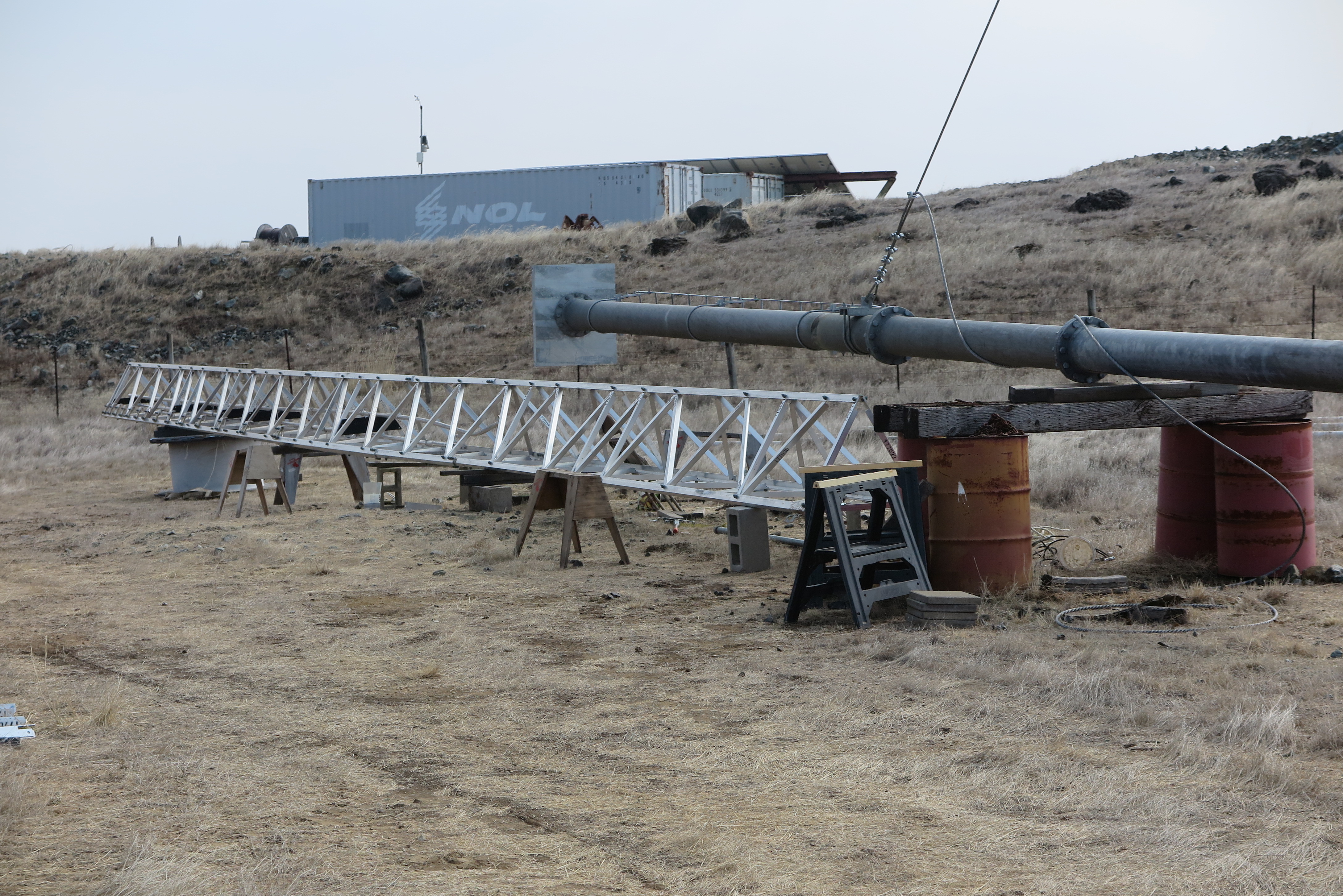
Reconstructed Boom
The image is of the reconstructed boom with the original undamaged front sections, to the reconstructed middle and rear sections.
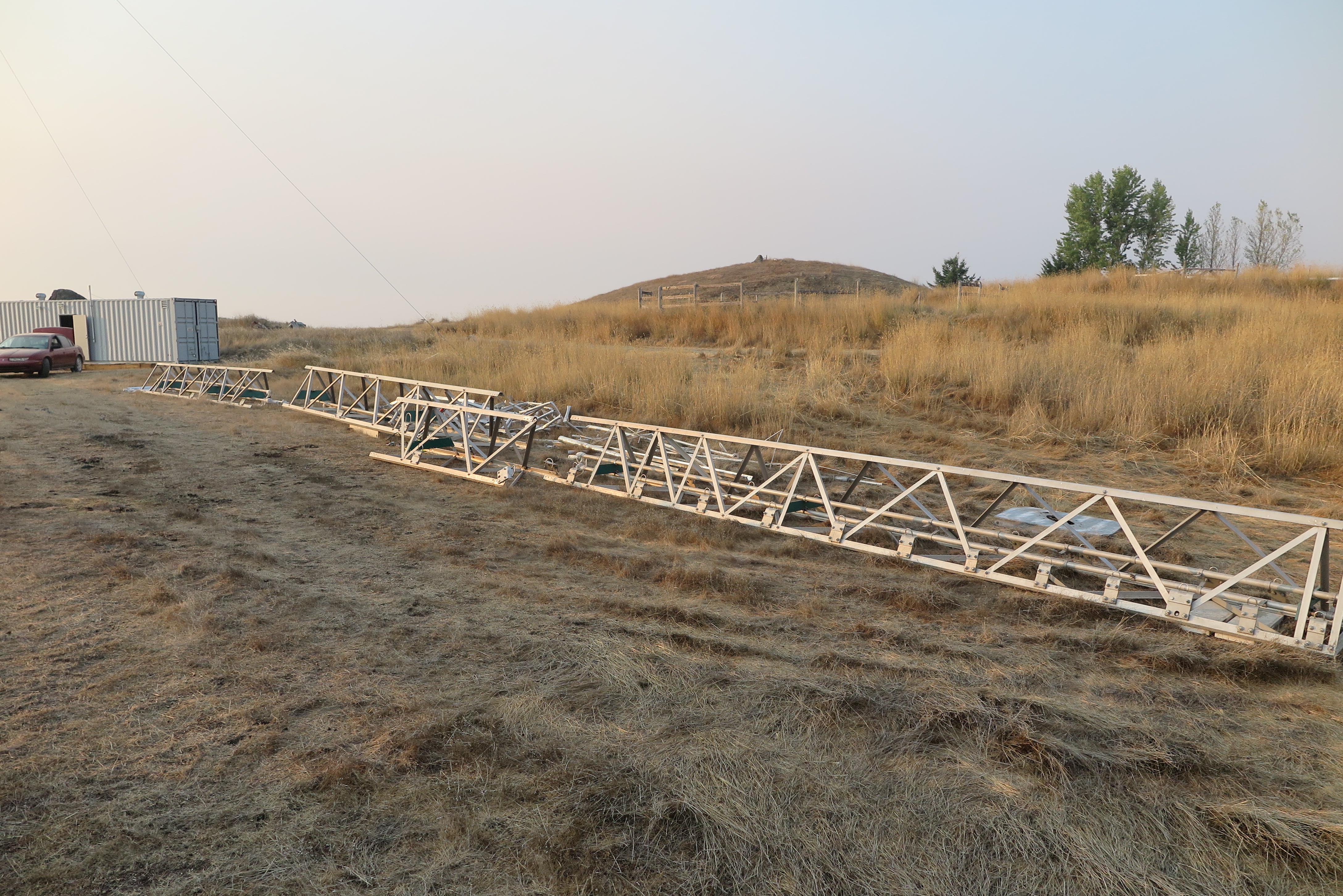
KLM Airlines LP1005A
After receiving the new aluminum from USAP, I received a call from a ham in Southern California who said he just heard of my misfortune, and had an LP1005, identical to mine, in storage! I mean, what are the chances? Further, he said he would not be able to use it, and he could sell it to me for replacement parts. We agreed on a price, with his agreeing to deliver it to my ranch, and off I go. I only wish he had found out about the accident sooner.
His son delivered the most important parts, the boom (in sections), and the elements. Here it is laid out as it was delivered, ready for me to take the needed parts, and apply them to my boom.
The antenna itself was originally owned by KLM Airlines in the Netherlands, surplused by them, then purchased by the ham in So. Cal. where he shipped it from Europe to the US.

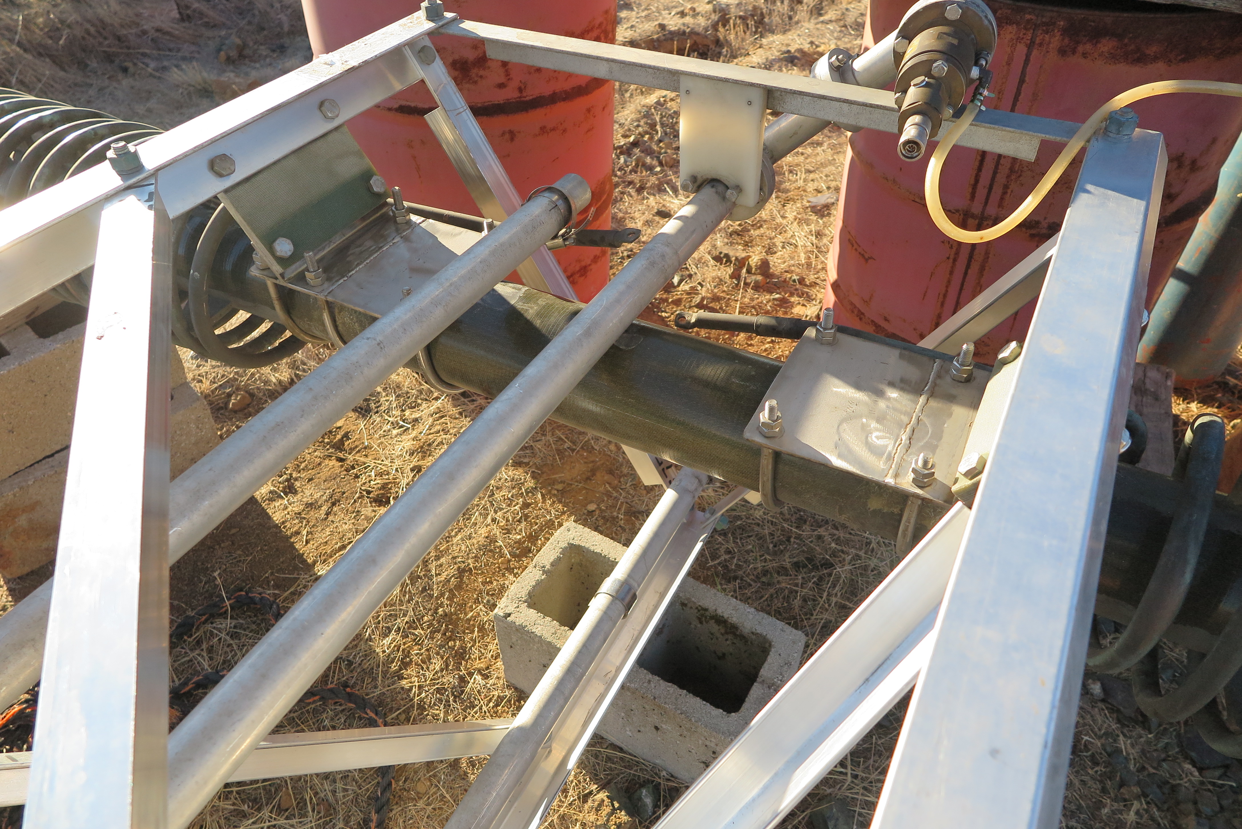
Backhoe Hydraulics to Winch
The 410G has an auxiliary hydraulic on the boom which I have connected to the 48,000 pound pull winch. The new wire rope pull cable is now 5/8 inch, up from 1/2, just to improve my safety margin. This is the largest wire rope allowed by the antenna hardware.
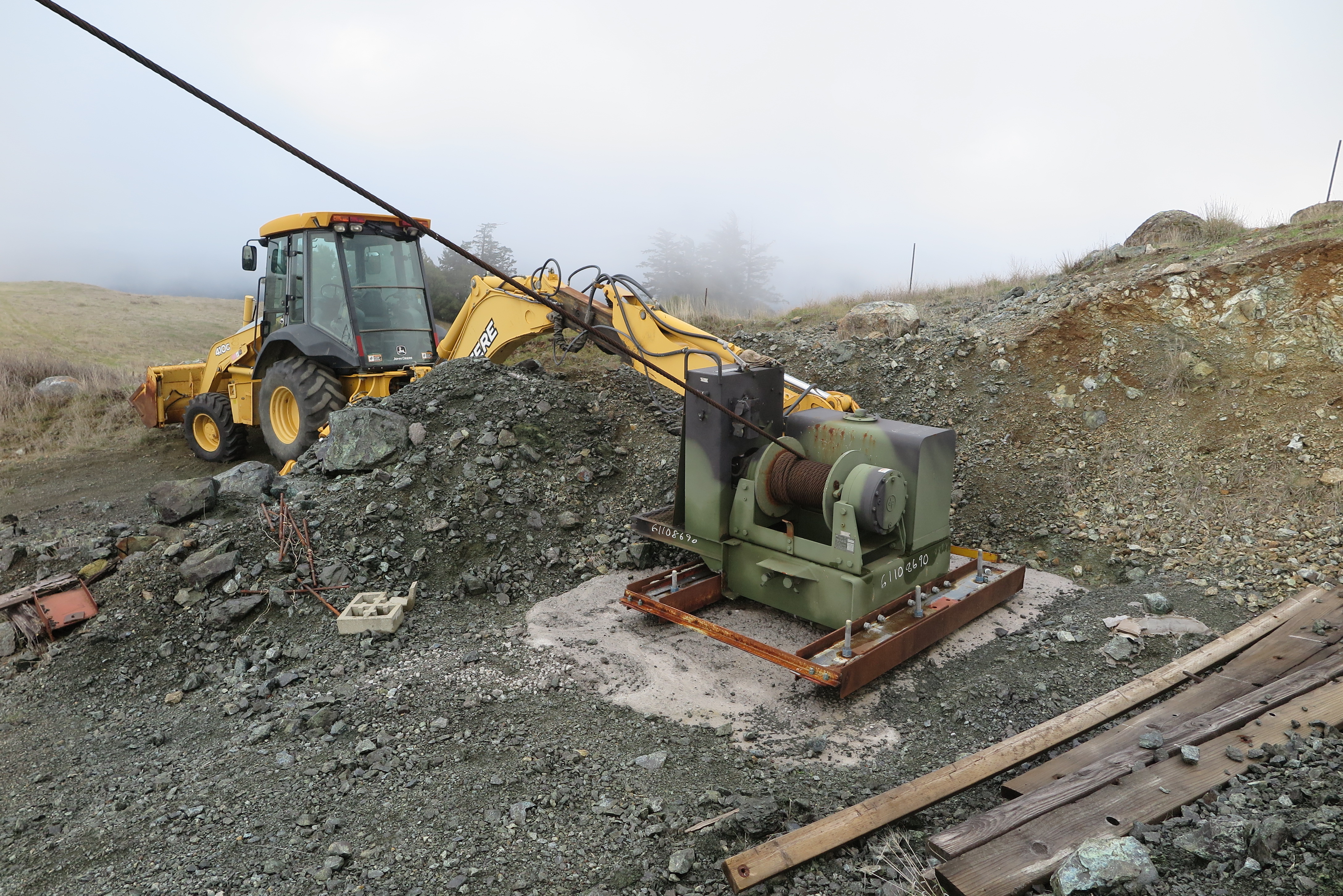
48000 Pound Pull Winch
Close-up of the winch. There are two items to worry about: first is I am concerned that those bolts sunk into the concrete will pull out of the cross I-beam webs. I have the shovel of the backhoe resting on the back left side, but the right could still pull through the steel beams. Before the big lift, I am going to try and find some square steel plates to put over those bolts to at least obtain more area on the steel web. The other issue is that the whole winch is at a slight angle to the tower, and I hope the wire rope will wind on the spool correctly.
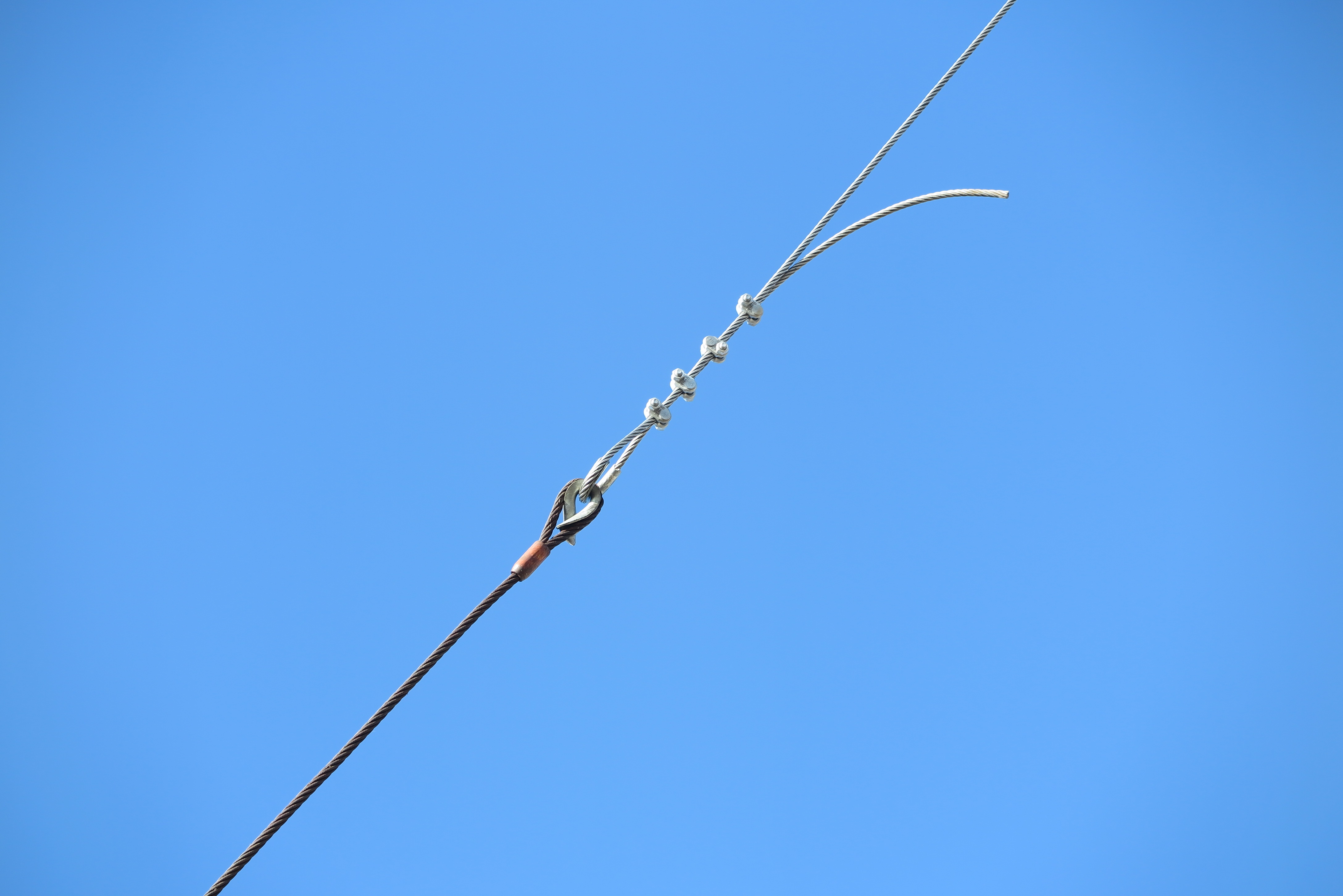
Winch to Pull Cable Interface
My "accident" on the first antenna disaster was caused by this interface where I had not torqued the wire rope clips to specification, and the wire rope slipped out. That is not going to happen twice. Now I have Crosley clamps on 5/8" rope, and have torqued each of these to the 130 foot pounds required. The larger cable comes up from the winch and is 7/8" in diameter, meeting my hoist cable at 5/8" diameter.

Boom and Mast Truss Joined
Here is the completed repaired boom truss, now bolted to the mast plate. I have completed two weeks work thanks to some terrific weather. Some days, thanks to California wildfires, I had to work in dense smoke, with an N95 mask for protection.

Right Side of Antenna and Mast
Another view of the mated boom and mast. Getting those two mast plate bolts in was a real bear. With two people, it would have been much easier!!
Pressure Test Feed line
Here is the first pressure test of the 50 Ohm coax feed line which goes up 100 feet through the center of the mast. The only leaks, and they were small, were in the rotary joint, and the 1 5/8" EIA-to-N adapter.

First Element 19 Installed
Déjà vu - Been here before, with the longest, heaviest element 19 installed. All the graduated pipe sections to get to 104 feet will be for another day.
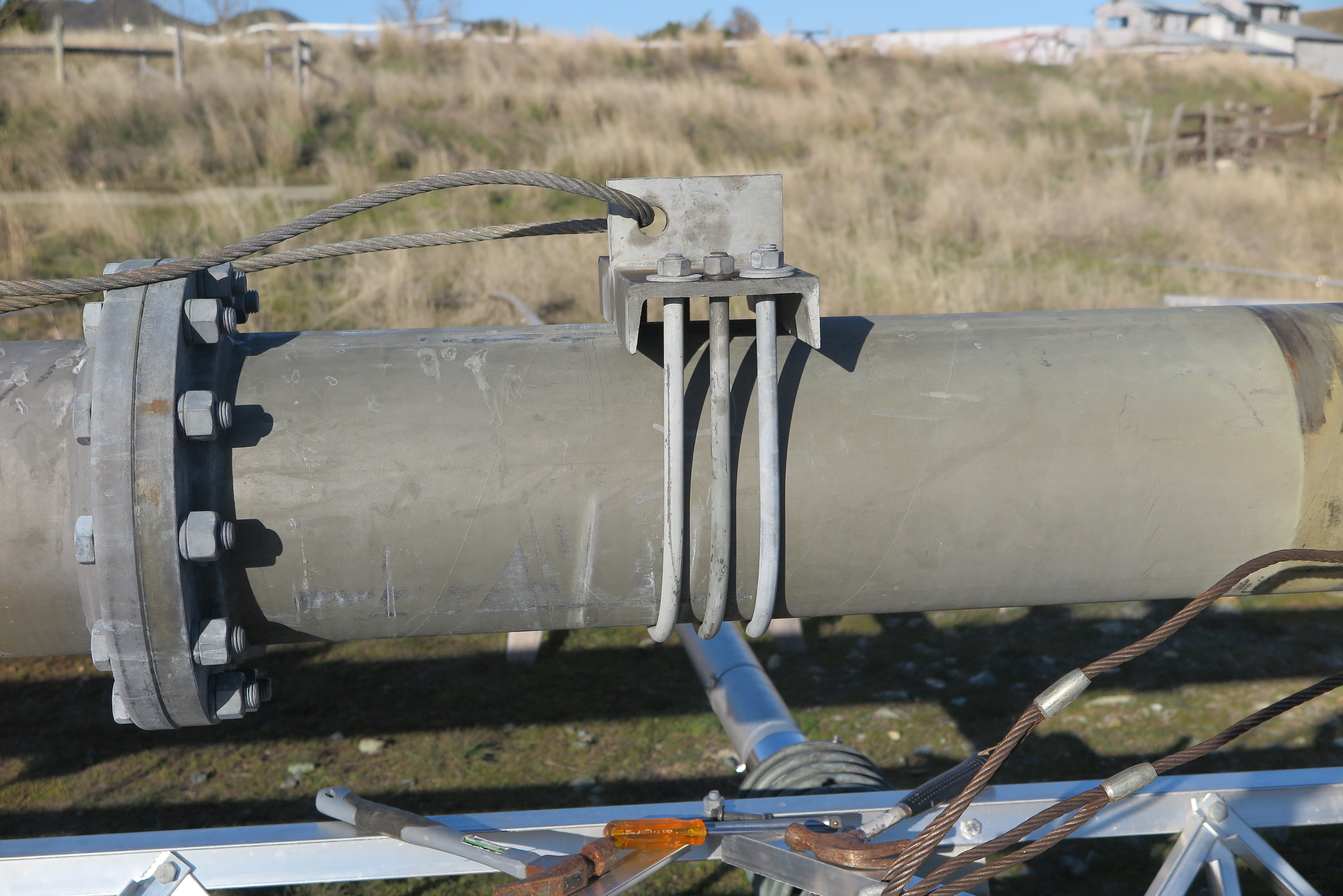
Look at that hefty mount!
Well that's more like it! Someone fabricated those three U-bolt mounting plates, a far cry from USAP's flimsy single U-Bolt fastener. I guess at either Tri_Ex or maybe KLM airlines, they too had a failure of that single U-Bolt connection and fashioned a much better engineered mounting plate. That sucker is never going to fail in heavy winds again.
Elements 16 through 19 Installed
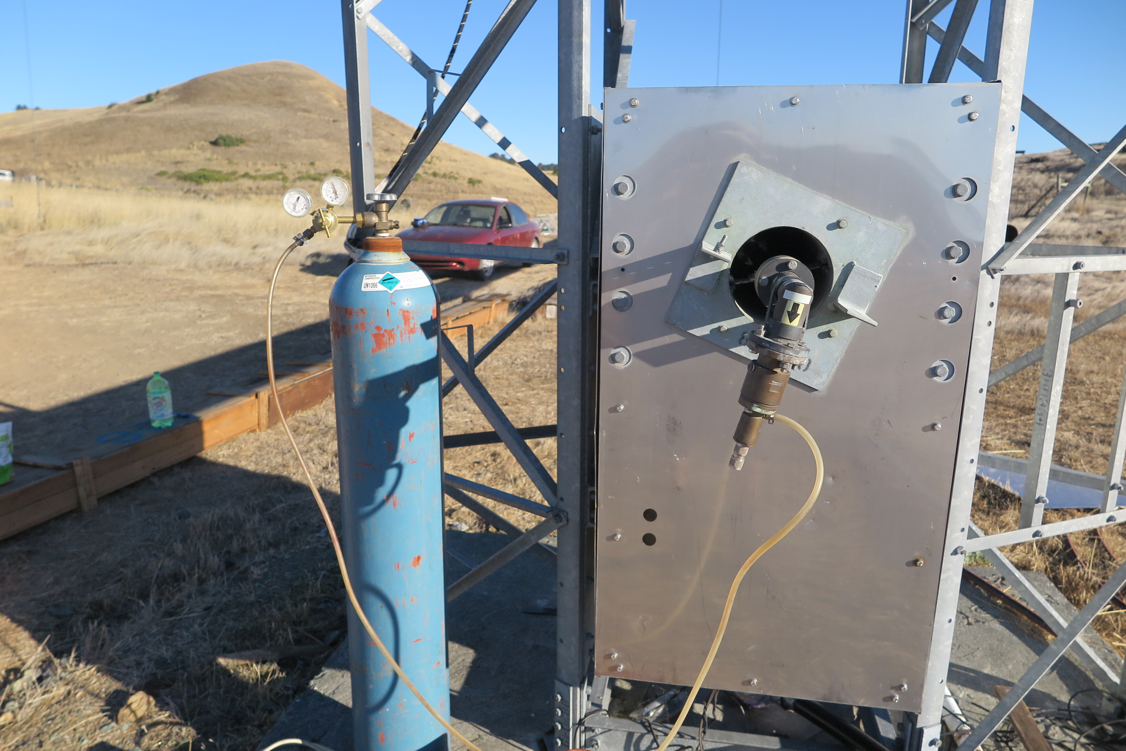
It's Monday November 9th, 2020, the last day of incredible weather for November, and I have elements 16 through 19 installed. These are the four that have the copper loading coils, and are quite heavy to place. The nitrogen bottle is to pressure test the tapered transmission line, which passed after placing some Teflon tape on one of the adapter fittings.
Not perfectly visible in this image is the completed tapered transmission line and the element feed, open wire transmission line. After using Time Domain Reflectometry (TDR) to plot the tapered transmission line's impedance vs. distance, it was clear that one section of the line was installed backwards. When placing the line in, I followed the person who disassembled the KLM antenna's markings where he had ends marked 5-to-5, 6-to-6 etc. so the antenna had to have been assembled incorrectly from the git-go. The TDR measurements were made with the VNA-2180 from Array Solutions. I altered the transmission line velocity factor to fine tune the distances, which are known. The result was 92% the speed of light, in very close agreement with the EIA 1 5/8 inch, air dielectric, hardline. The tapered transmission line Z0 begins at 50.1 Ohms and ends at 64 Ohms where it directly connects to an open-wire transmission line with a calculated Z0 of 120 Ohms. Note that is twice the impedance of the tapered transmission line, and at this point, I don't understand what is happening here. It's like there are two open wire lines in parallel?
An update to my not understanding thanks to K9WN, N6RK, and W7HPW. The dipole elements reflect an impedance which varies with physical design of the LP, and frequency, not to mention ground characteristics. Using "LPCAD" written by W8IO, using various design criteria, I could get the feed impedance to range from 100+ Ohms to over 400 Ohms! It's that impedance which appears in parallel with the impedance of the line itself, so it all balances out in the wash.
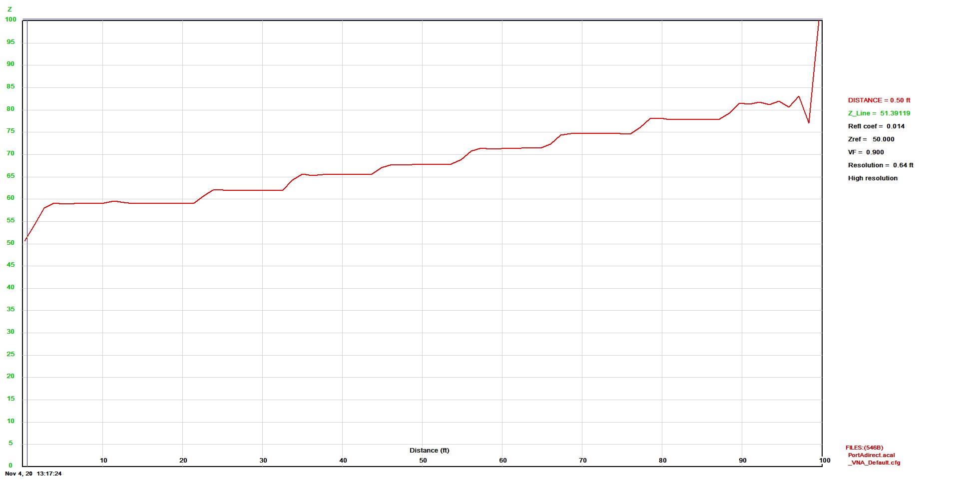
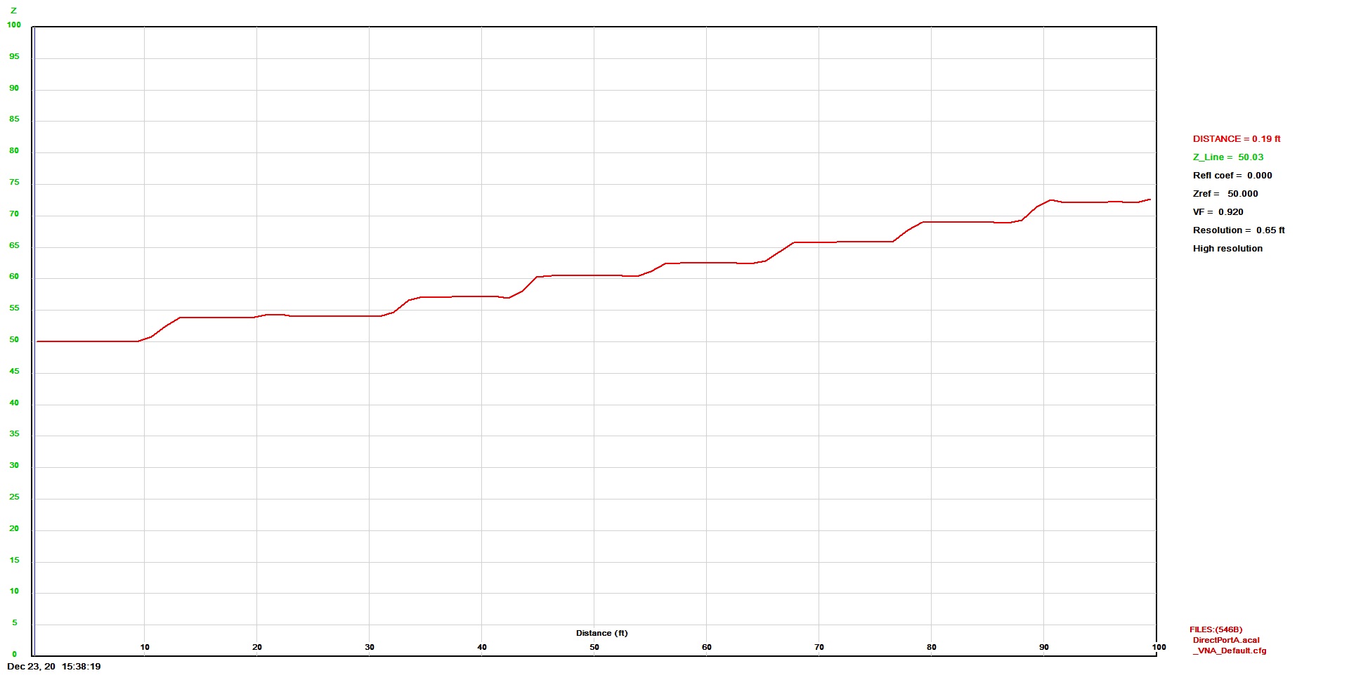
TDR of Tapered Transmission Line
Using a VNA in TDR mode, shows the impedance variation of the tapered transmission line vs. distance. Telex made the line by using sections of brass tubing of ever decreasing diameter, and brazing them together with Teflon spacers every few feet. (click on the image for full size in another tab)
The plot shows a sharp up slope from 50 Ohms to 58 Ohms at the start, and there is nothing I know of to physically account for that. This is a section that has several plumbed elbows, so I need to take each one apart and find out why the sudden jump. The first small bump at 10 feet is a coupling flange interface. Even though this plot ends at 83 Ohms or so, by measuring the diameter of the brass center conductor, and the inside diameter of the 1 5/8" EIA tube, I calculate the Z0 to be more like 73 Ohms.
TDR of Tapered Transmission Line
Here is a TDR plot with the correct transmission line impedance as a function of distance. The problem from the previous slide was my double elbow fix had a poor fitting center conductor which was also a smaller diameter than the 50 Ohm dimension type, and also my 1 5/8" EIA-to-N adapter had a poor connection internally. After correcting all that, I have this perfect impedance plot. (click on the image for full size in another tab)
Back Right View
I have all elements but the last long ones, 18 and 19 completed with a mix of my original antenna's parts, and the KLM antenna's parts. None of the element-to-element connecting stainless steel bolts were with the KLM antenna, so I have used what I have from the original antenna, but I'll have to buy those that were bent beyond usability in the crash.
Antenna Business End
Front view of the LP looking at element 1 and the coaxial-to-open wire line transition.
VSWR Plot
VSWR, return loss, and Zmag of the LP just a few feet off the ground and the longest 2 elements not at their design lengths. It's actually not too bad, save for the upper frequency end. The spec is SWR less than 2:1 from 4 MHz through 30 MHz, and less than 3:1 from 3 MHz through 4 MHz. As you can see, it doesn't make that specification, but I hope it is because it is so close to the ground. Being close to the ground increases the element-to-ground capacitance, and lowers the resonance frequency, thus, the elements at the high frequency end of the LP appear longer, so the VSWR goes up. When I begin raising the antenna, the high frequency end will go skyward first, so I can do another VNA sweep at that angle and hopefully see an improvement on that high end.
(click on the plot for a larger image in a new tab)
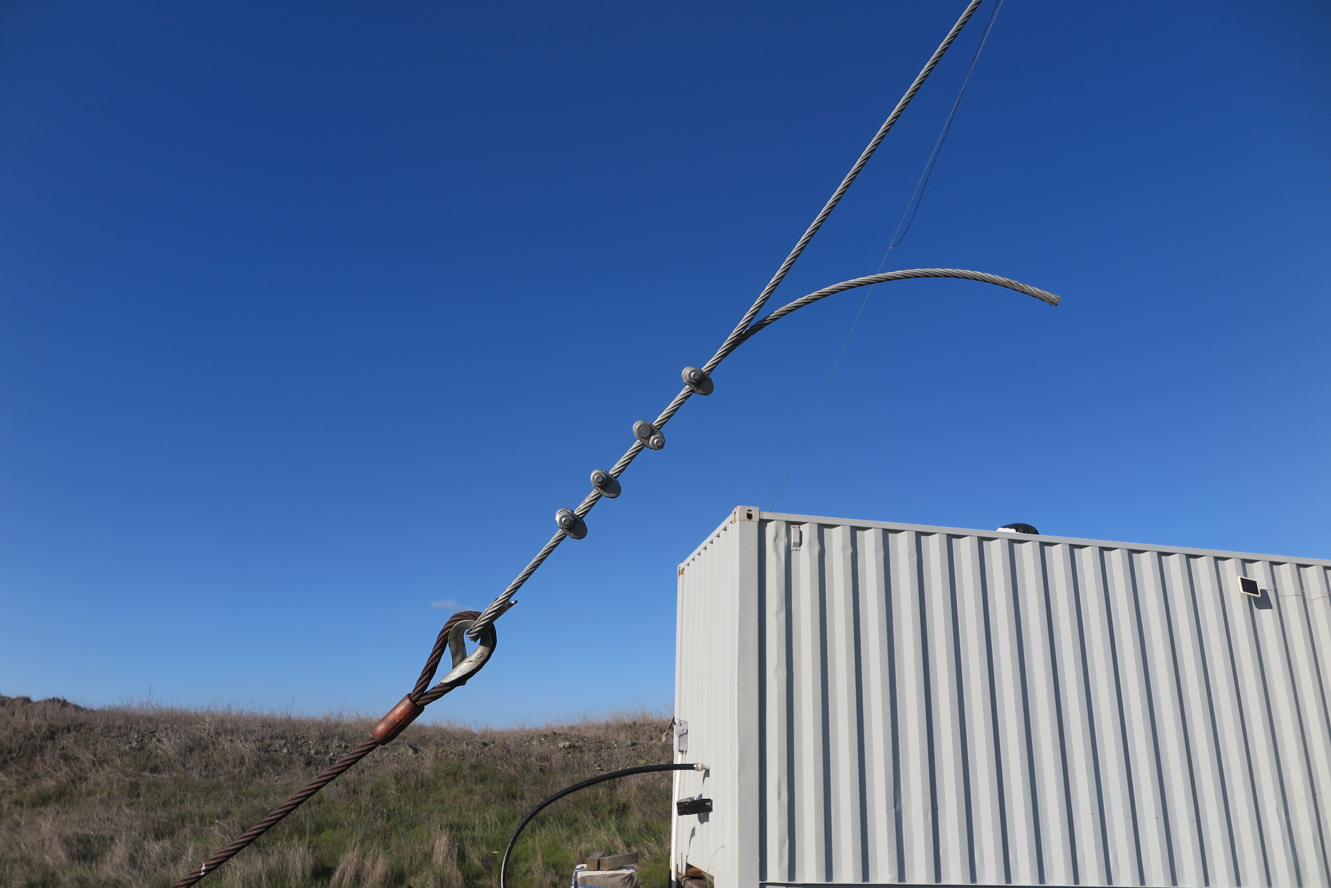
Pull Up Block
I have been looking over the entire antenna and ground support equipment for weak points. The U-bolts on this pull up block had bends at the thread end, so to reinforce the design, I drilled another 2 holes in the center, and installed a 3rd U-bolt. To my horror, when I went to loosen the clamps that are holding the wire rope, the same clamps I had torqued to 130 foot pounds, they were almost loose. This of course was the very way my first failure happened. There are 4 clamps on the pull down side, and I figured I had no choice but to lower those to the ground and retorque them.
Pull Down Clamps
After a LOT of extra work, I have the pull down side clamps where I can reach them from the ground. None of them was anywhere near the 130 foot pounds I had torqued them to when I first installed them, but at least they weren't loose. I now have retorqued them twice to the recommended 130 foot pounds.
Incidentally, I have calculated the pull force on the wire rope at the mast junction is ~10,600 pounds. USAP recommends a 6000 pound pull force winch - No Way! Maybe they meant 16,000 pounds which is much more realistic.
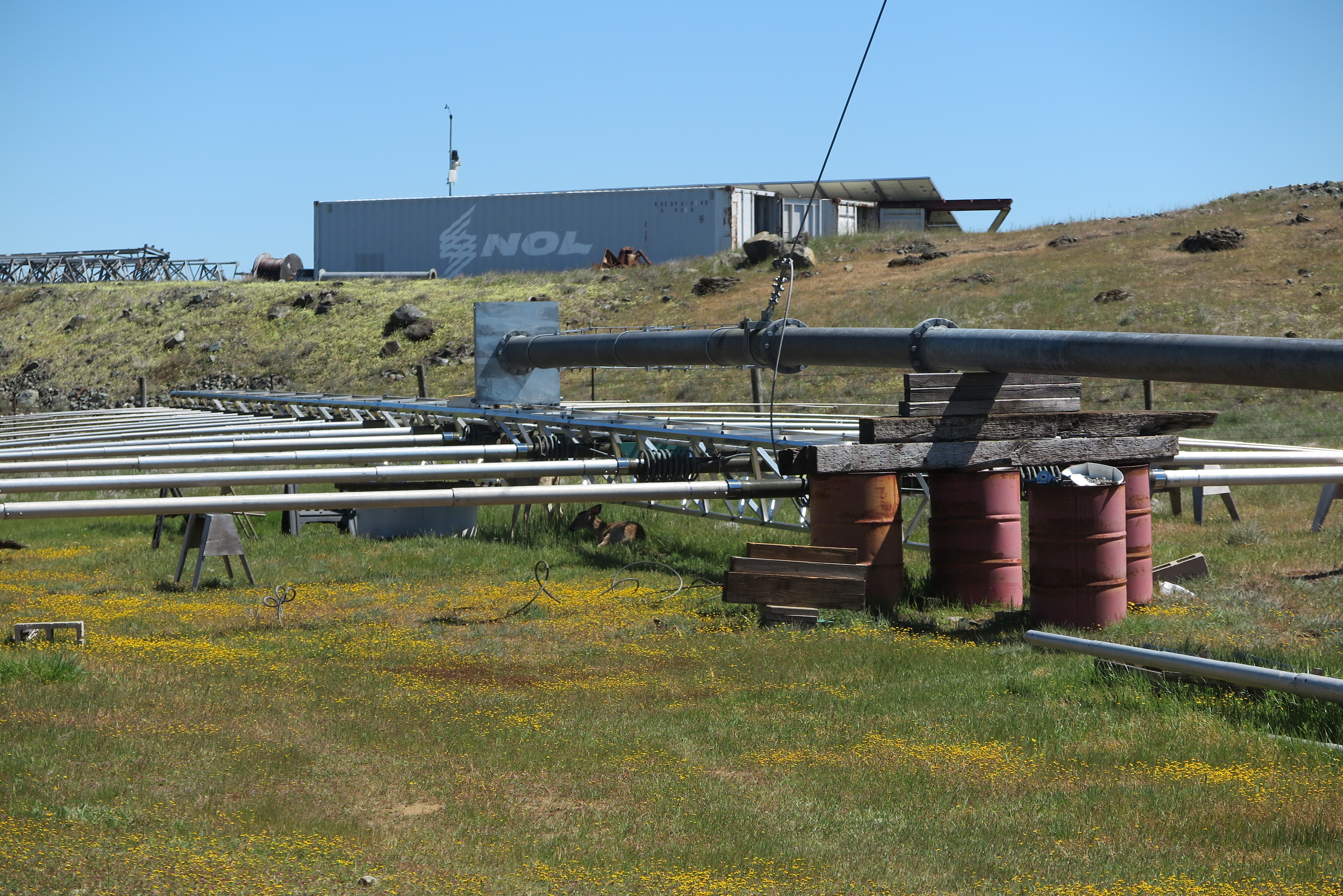
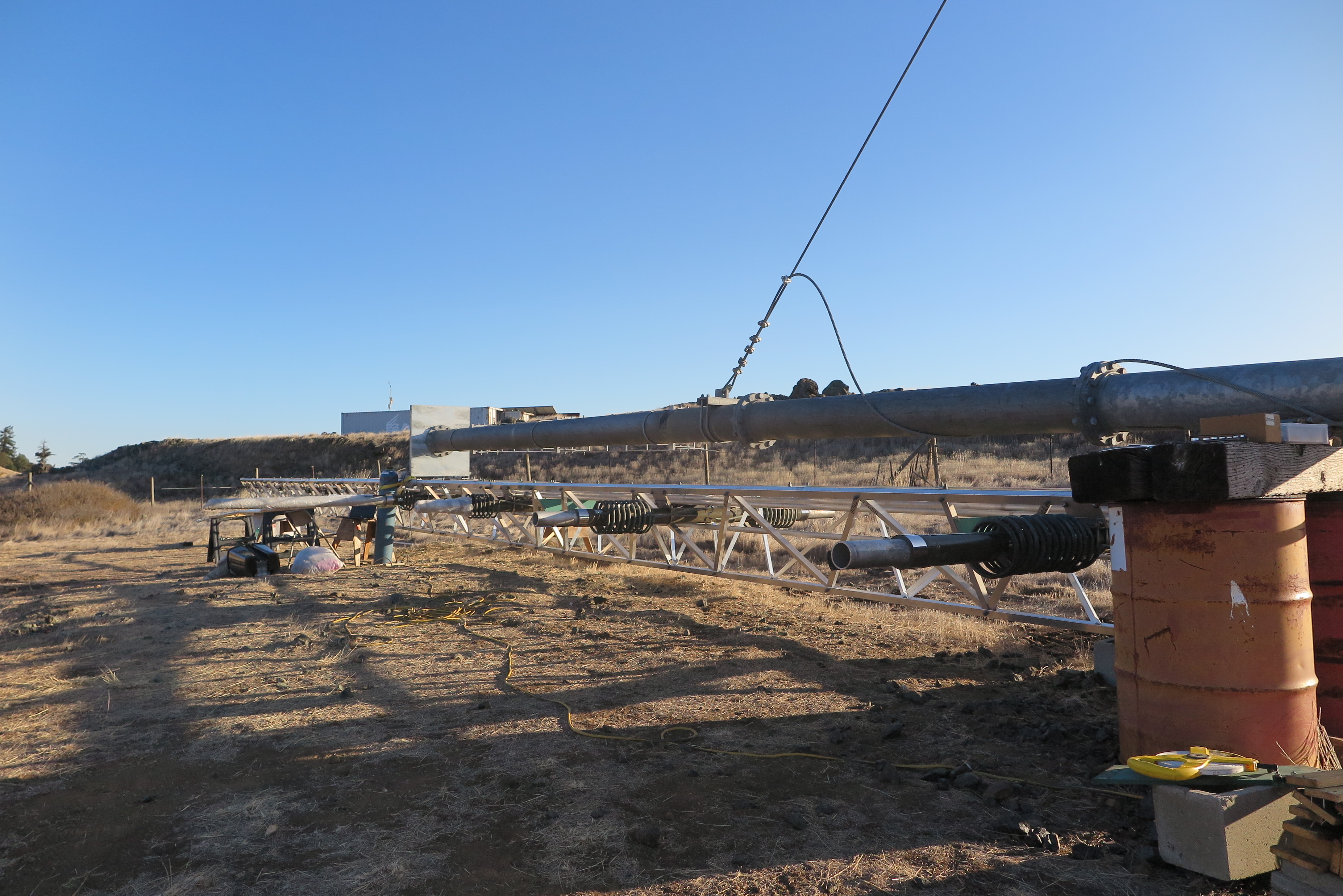
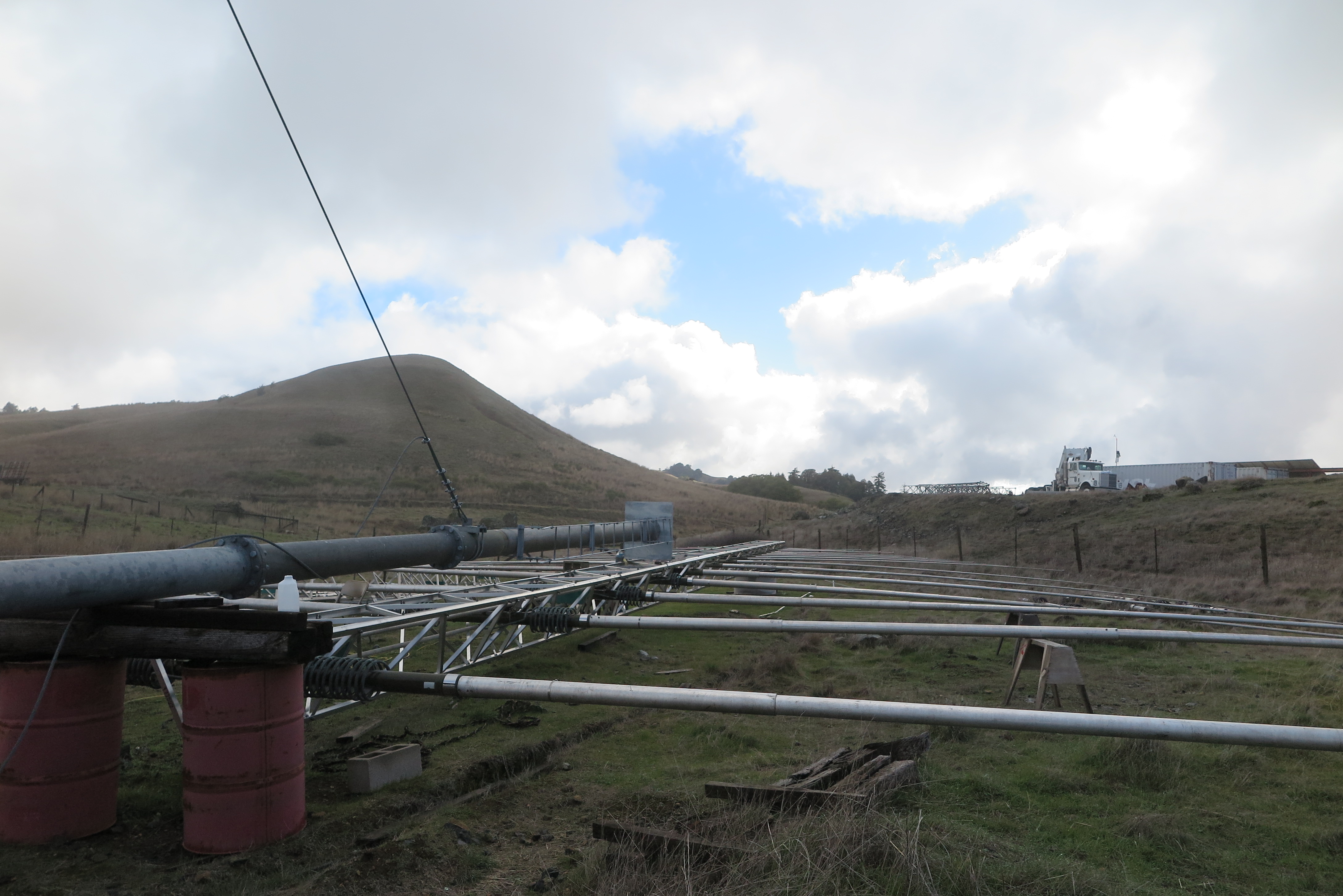
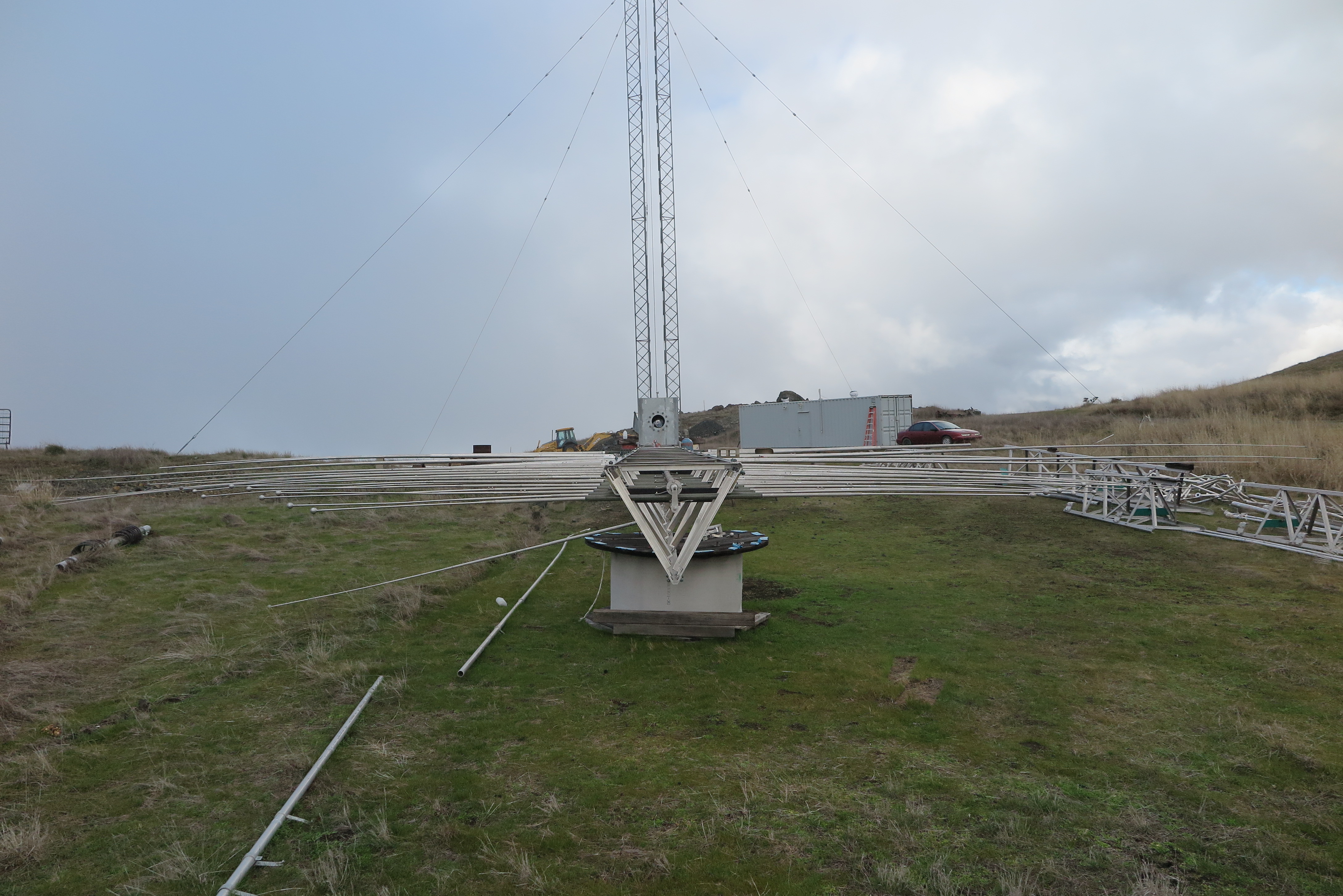
Ready to Erect
Here is the complete antenna from the backside ready to be erected (again). The deer have promised to help...
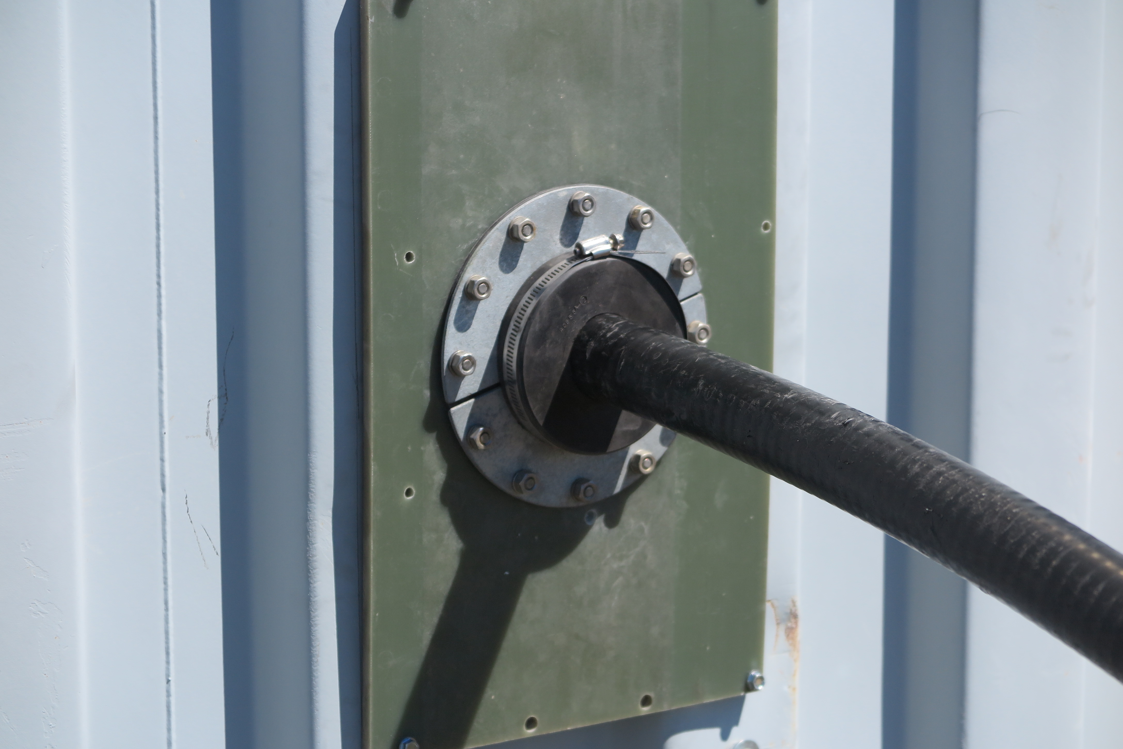
Heliax Entry to Shack
This has nothing to do with restoring the antenna, but I thought I should get rid of my tinker-toy previous heliax-to-shack interface. This is an Andrew approved clamp and weather proof heliax penetration into the shack.
Missing Ring
Note the small ring wrapping the Teflon spacer. I noticed a fairly large bump in the |Z| vs. distance with the VNA in TDR mode. After a LOT of investigation, I finally traced the problem to one flange interface without that stainless steel ring which completes the continuity of the inside diameter of the rigid coax interface. Without that ring, there is a gap in the shield of the coax, forcing the currents trying to flow there, to take a longer route through the bolts. After supplying the needed ring, that problem went away.

Complete Antenna Test Pull
I had some technical visitors at site, three of whom were hams, looking to see if my site up here would be useful as a repeater location. Since I had some moral support, I went ahead and winched the antenna off the ground. It reached about 20 degrees without incident, so I nestled it back down to horizontal, and am now a lot more confident that I will be able to raise the antenna when I'm finally ready.
Corroded Hardware
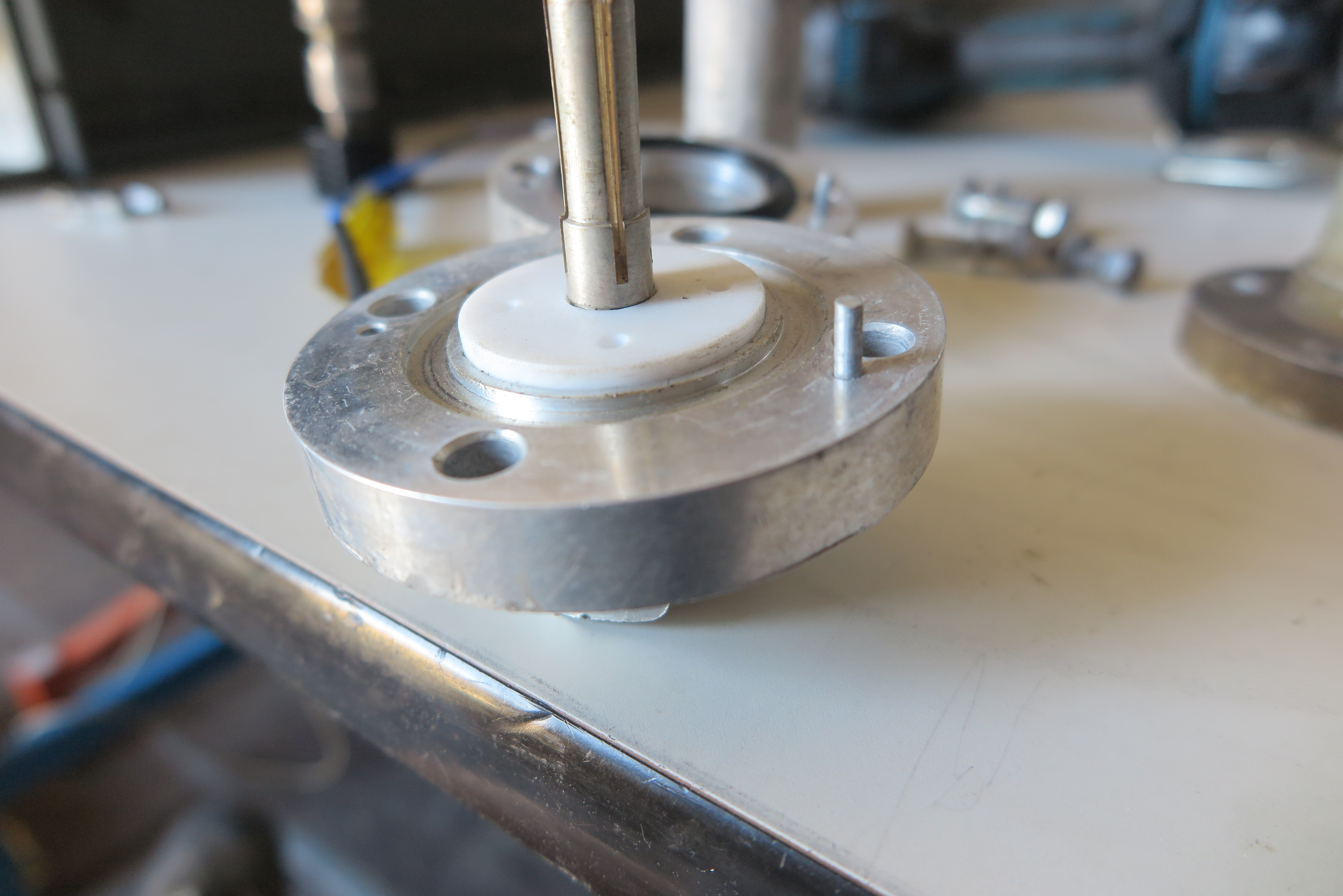
So it's now June 2021, and I am really close to raising the antenna back to vertical, when I decide to make sure each element has a solid connection to the open wire transmission line. To my shock, six elements had resistances of from 4 to 6 Ohms rather than zero Ohms.
There are stainless steel bolts whose heads rest near the end of any individual dipole half-element in a recessed pocket in the fiberglass insulator, and then protrude through the other side of the element where an aluminum spacer brings the electrical connection to the element at the surface. At that point a strap connects the dipole half to the open wire transmission line. Well, as you can see, there is heavy corrosion on the bolt's head, both sides of the aluminum spacer, and the element itself visible in the bottom of the hole.
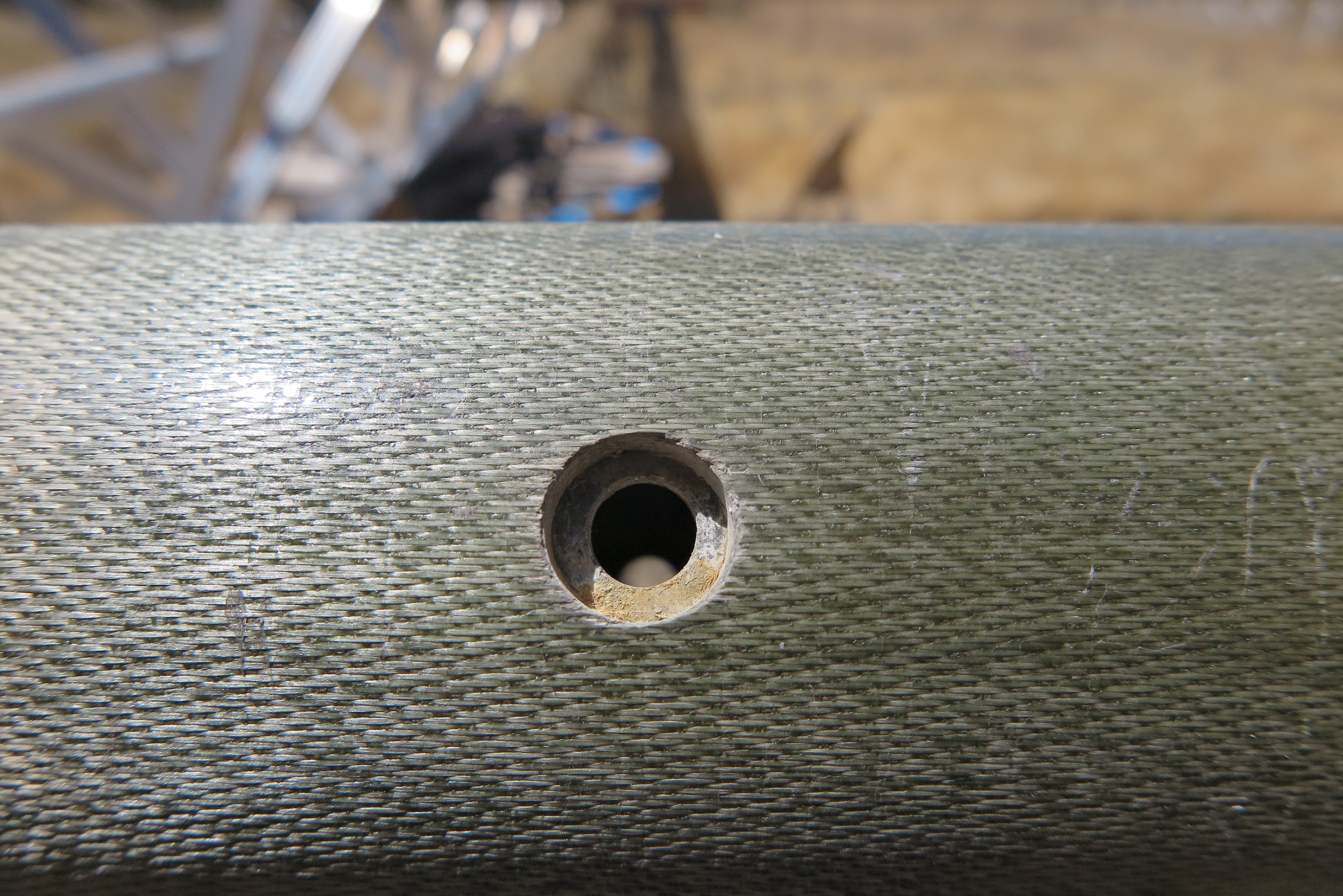
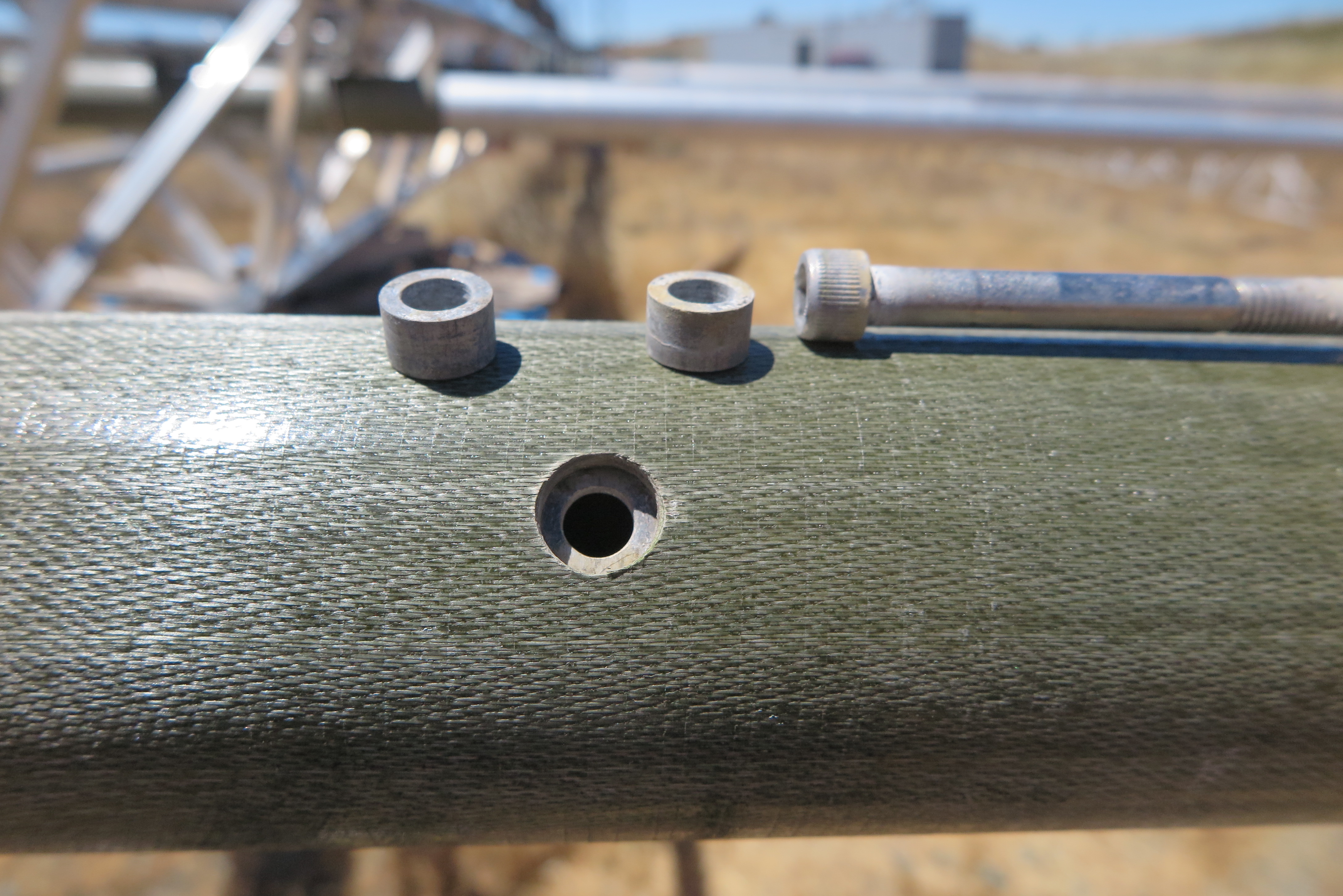
Corroded Element Connection
It takes about a half hour to clean each of the smaller elements, and about an hour to clean the bigger ones, but I have no choice, I have to do every one of them, even those that read zero Ohms, since I suspect there is corrosion in all of them.
Not sure how I'll seal these connections from further moisture collection, but maybe leaving them open so water evaporates is a better solution. I noted that even those bolt heads that had a sealant all around them, still had lots of corrosion.
Pull Down Antenna
I asked a local ham, Jon KK6WS to help raise this beast, and I'm sure glad he came up to the ranch. Here we are pulling the back end of the antenna which pivots at the mast plate, to get the antenna perpendicular to the mast.
On any of the images, if you click on the image, it will load a full-size image in another tab, for better viewing.

Antenna-to-Mast Attach
Once the antenna is orthogonal to the mast, it gets bolted to the mast plate with 4 big nuts and bolts. After that, the feed line flange needs to be mated to the mast feed line. After a couple hours up there, I got heat stroke, and had to come down. Fortunately, Jon was willing to finish the task. He is a retired United Airlines master mechanic, so he was right at home with all the hardware.

Removing Crossmember
I took off 5 turns from each of the two turnbuckles facing the antenna to relieve a lot of the stress on the twin towers when the upper cross member is removed to allow the mast to nest into the rear bearing half. I still didn't feel up to climbing up the tower to do that, so again Jon saved the day. In this image he is removing that piece of channel which bolts to the towers on the antenna facing side. I also have a large turnbuckle linking the twin towers to pull them together when the channel has to go back on. I'll do that on another day after the antenna is vertical.
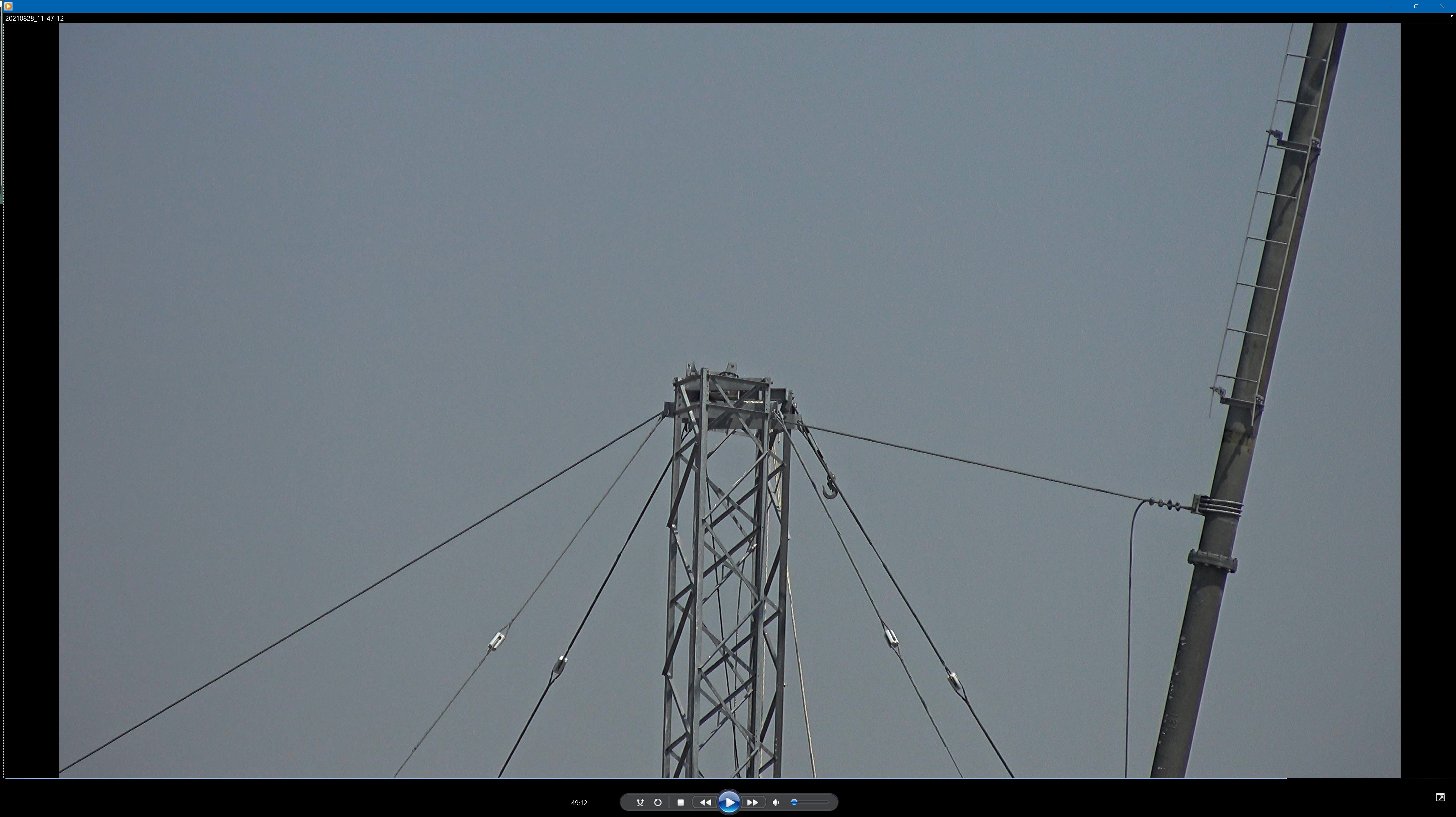
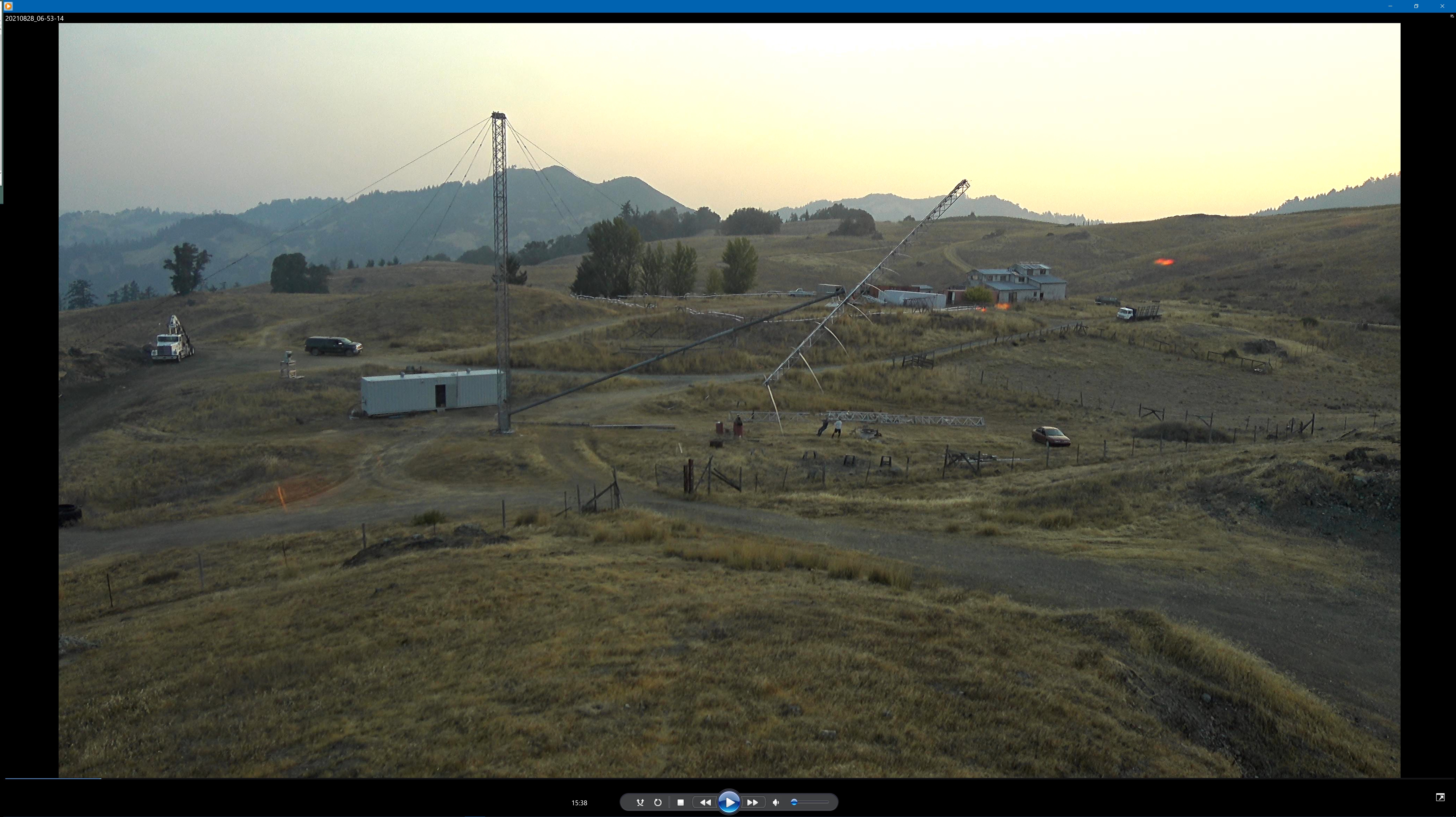
Mast Near Vertical
At this point the winch has done its thing and the mast is almost to vertical. Jon is watching from the side, telling me via a walkie-talkie how much more cable to pull up.
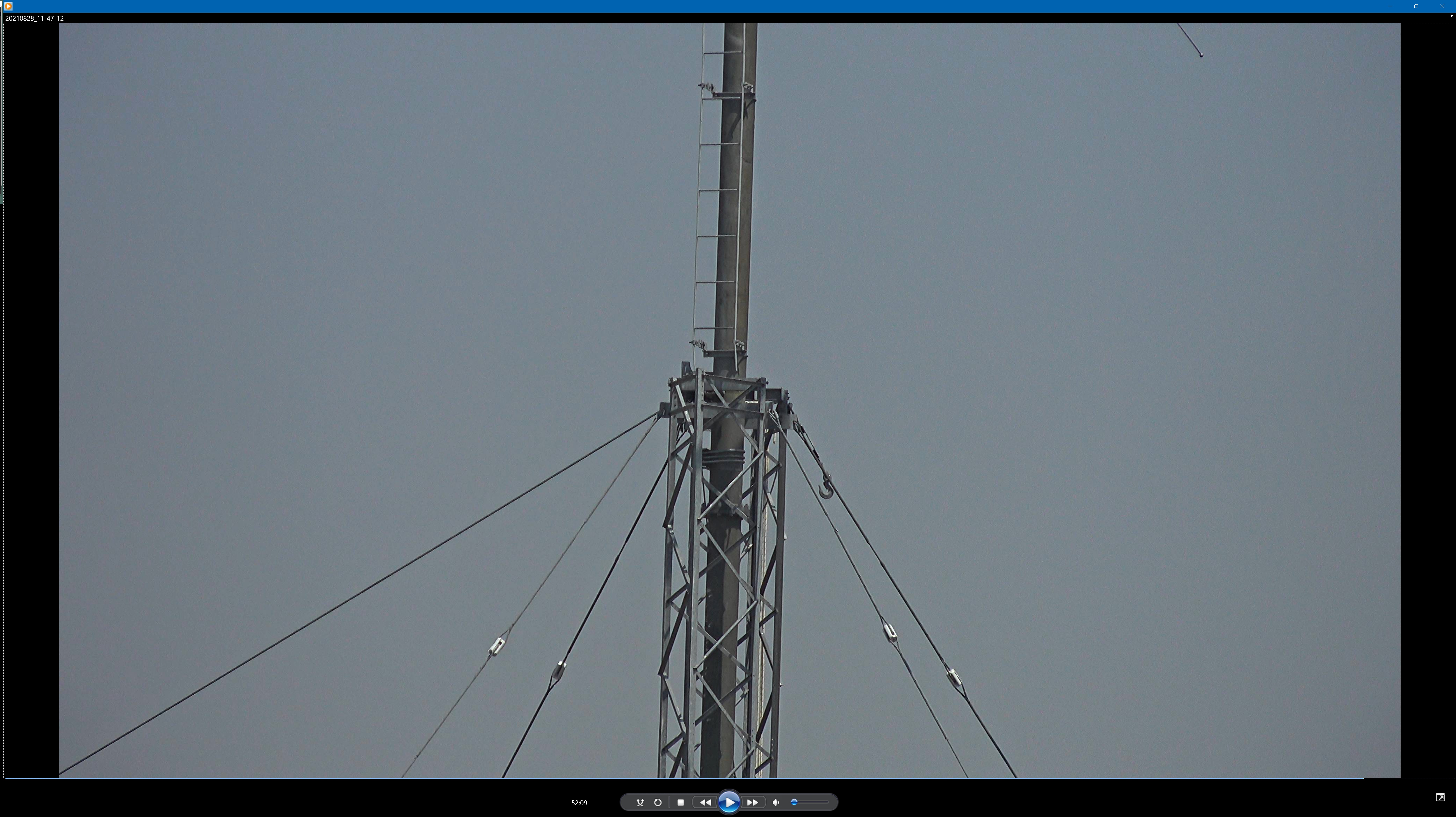
Mast Vertical
Finally this baby is up! The winch pull cable is pretty much holding the antenna up there, but I was very worried about impending winds. It wasn't until the following day that I felt up to replacing the channel crossmember, and the bearing half itself. It took about two hours to get it all back together.
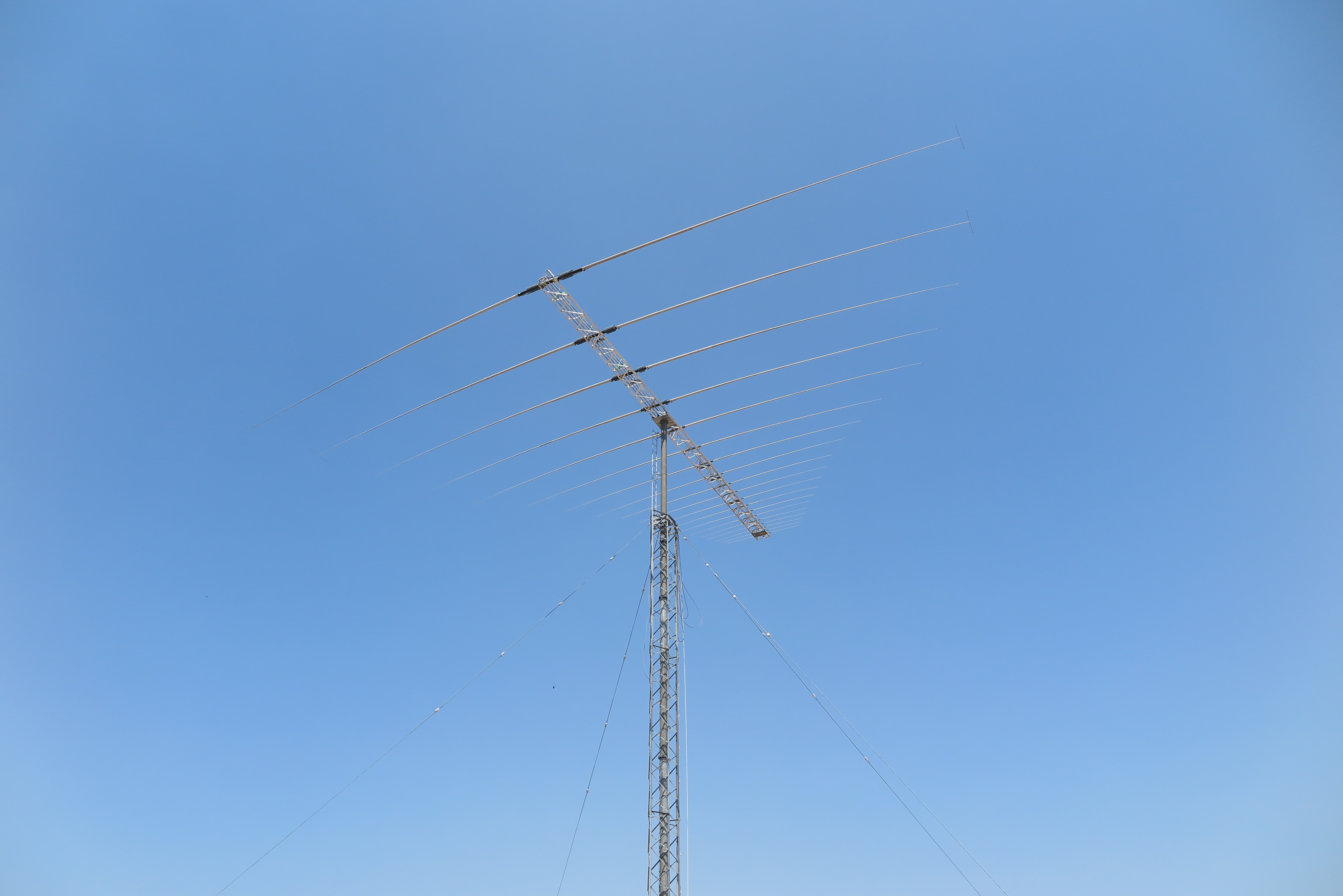
Finally Up
There she is again. I have now connected the transmission line to the shack, and have pressurized the transmission line with nitrogen at 10 PSI. There seem to be very few leaks, although I'll have to wait a month-or-so to see how much nitrogen gets lost. I have a full size tank in the shack which has started out at about 1200 PSI, down from 2000 PSI after the tank had been refilled.
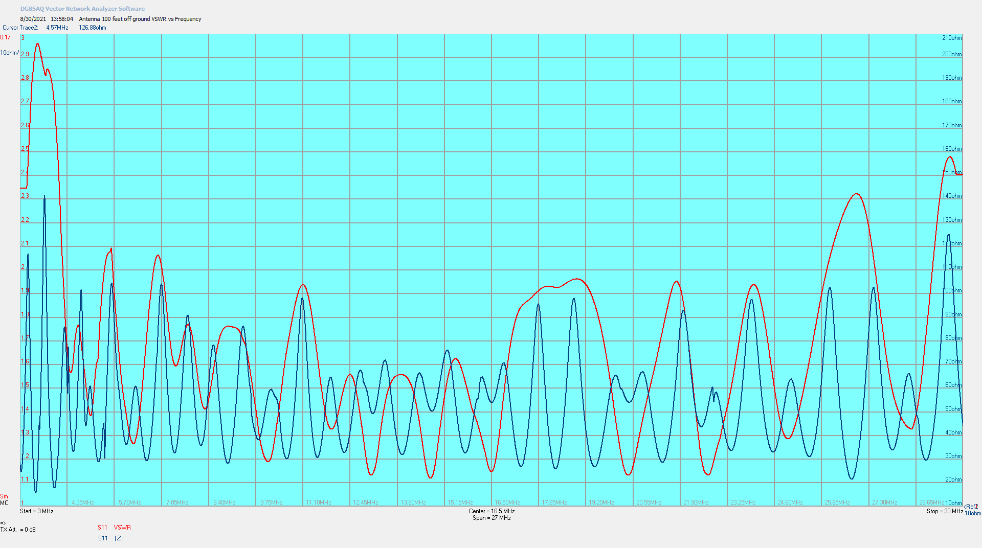
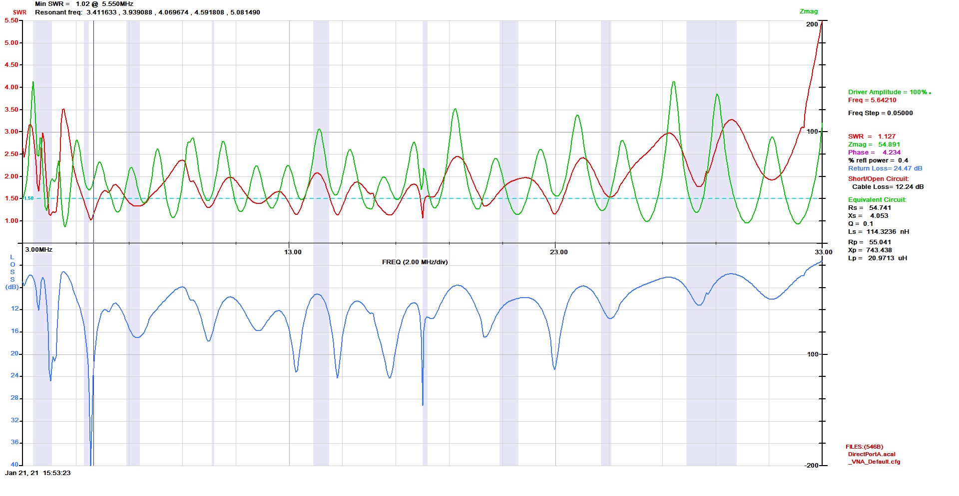
Final VSWR
Here is a sweep from 3 MHz through 30 MHz with the LPDA at 100 feet. It actually meets the manufacture's specification, but I'll still need an antenna tuner for 80, 75, 15, and 10 meters. The red is VSWR, and the blue is |Z|.
Click on the image, it will load a full-size graphic in another tab, for easier viewing.