e-mail: doug@dougronald.com
Solar Power Plant
My ranch in Mendocino County needed power, and it was not feasible to connect to the grid. Solar and wind were the options, and solar was first, since there are some 240 days of sun at this location. My planning suggested I needed 25 amps at 48 VDC for 7 days continuous, which sized the plant. I decided on 6.6 kW for the solar array, and 1760 amp hours for the battery capacity.
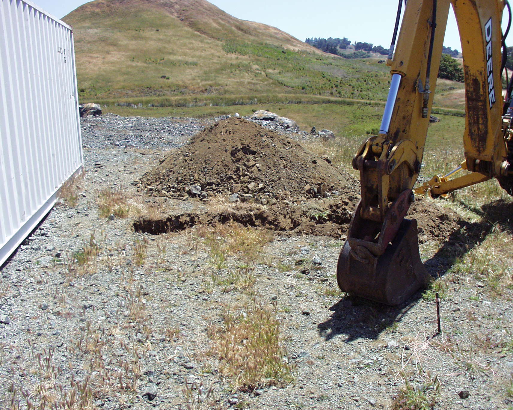
Digging First Foundation Hole
I'm using my Deere 410G Backhoe/Loader to dig out the first support foundation hole. There will be three of these holes to support the array of PV panels.
The 40' ISO container next to the hole will house the electronics; namely the batteries, the charger, the inverter, and the monitoring computer.
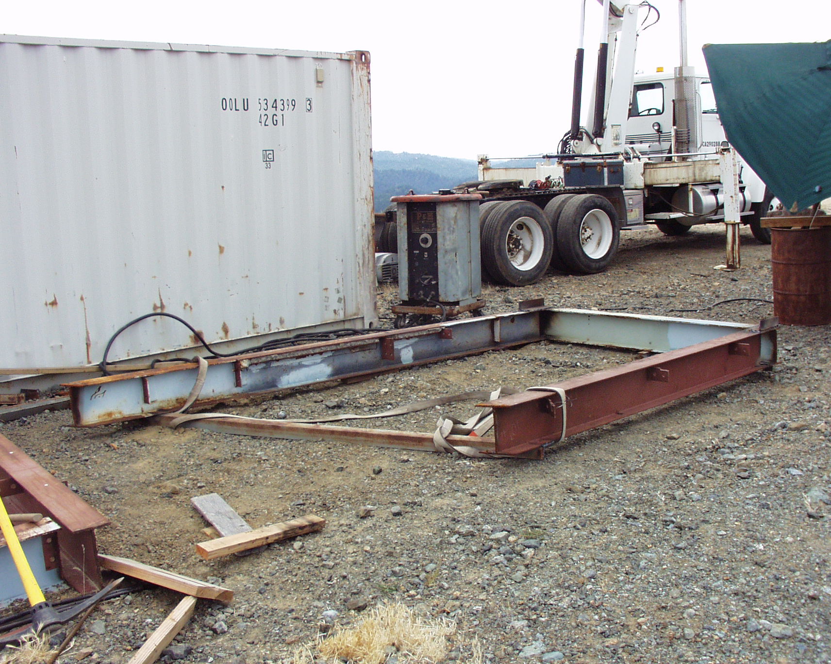
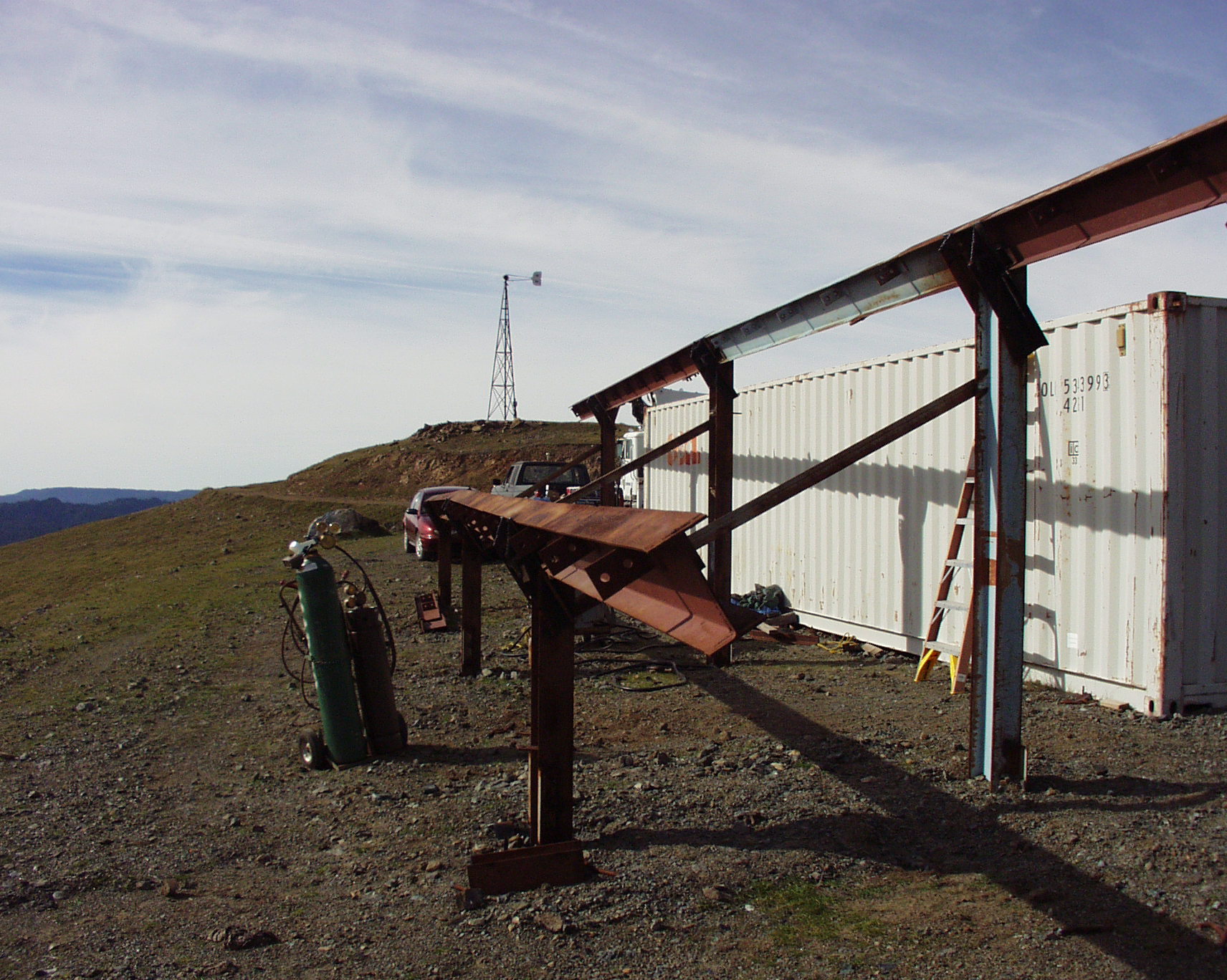
Welding the First Support Weldment
I welded these steel beams in a structure that is intended to support the solar array. This was the first one to be constructed.
Someone might note that the steel beams seem a bit heavy for this application, and that is true. I could have built a skyscraper with this steel, but I was given it for the cost of taking it away, and that offer I couldn't refuse, especially since I had the trackor-trailer with an attached crane.
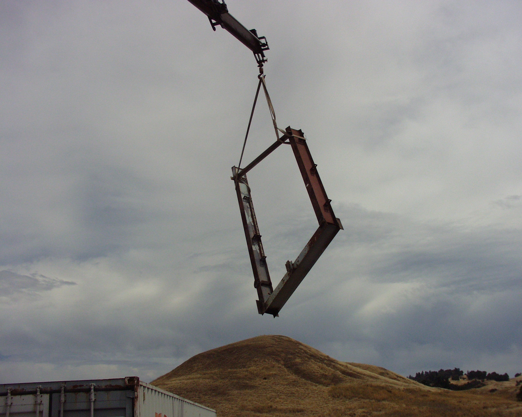
First Weldment on Crane
Using my truck crane to lift the first support weldment over the 40' container to it's foundation hole.
First Weldment in Ground
Here is the first support structure in the east hole.
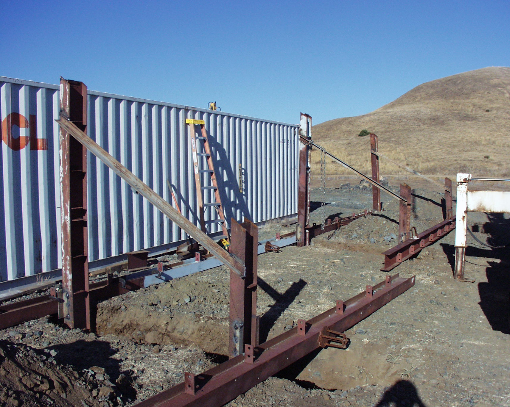
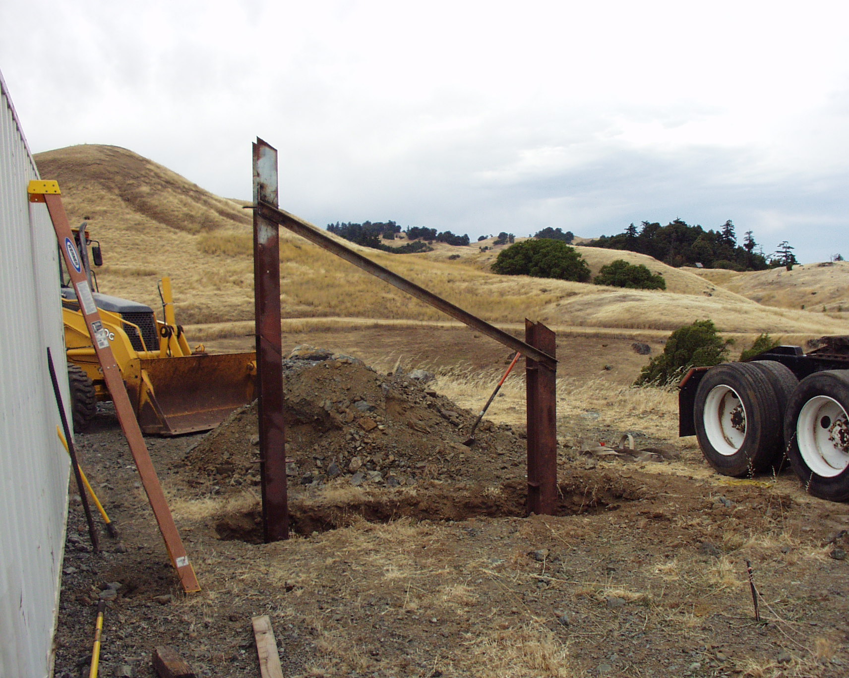
Three Supports in Ground
At this point, I have the three main supports in their foundation holes and am about to align them with the long beams on the ground. I welded plates to the legs of the supports to enable me to clamp the long beams firmly in alignment as the concrete is poured.
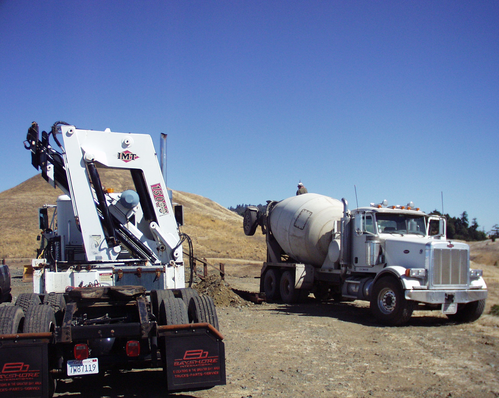
Concrete Pour
Only one truck with a partial load was required to fill the three support weldments, and secure them forever in the earth.
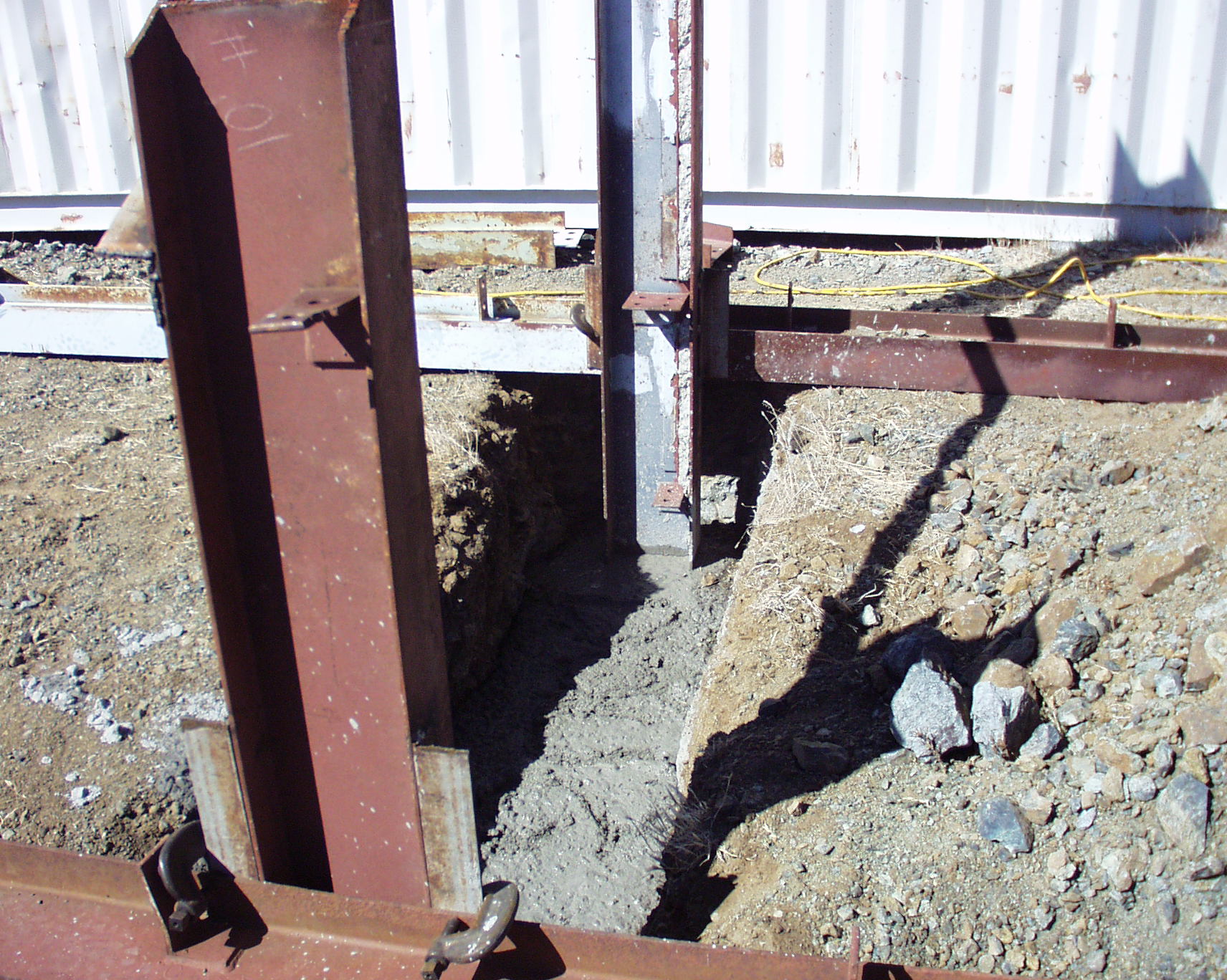
Concrete In East Leg
I used the horizontal beams to keep the legs in perfect alignment as the concrete was poured. These long beams will be the horizontal supports for the vertical runners that the PV panels will be attached to.
On this mountain ridge, I get some hellacious winds, so these I-beams give me a lot of reassurance that the whole array won't blow away.
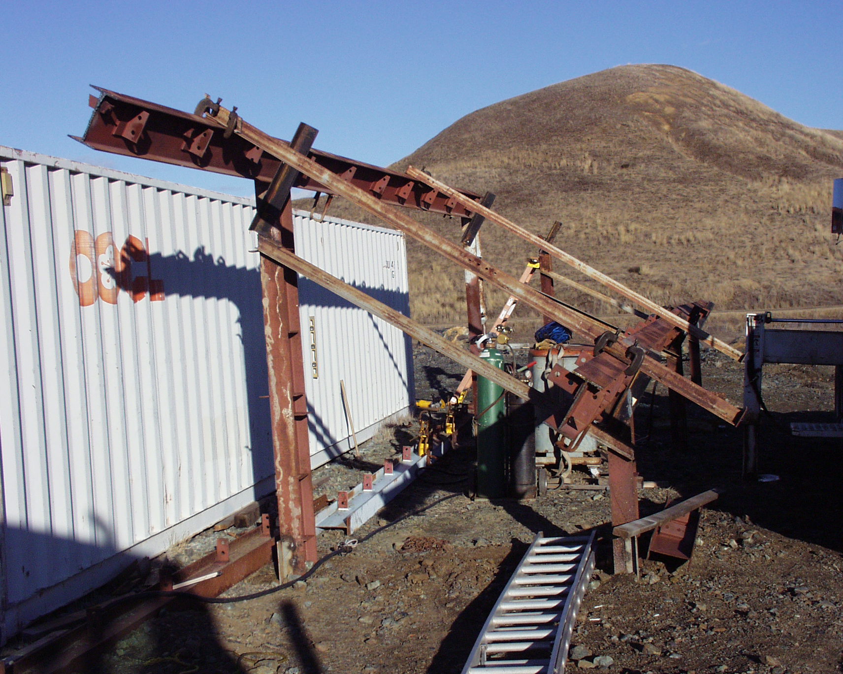
Ready to Weld Cross Beams
I used the crane to position the cross beams on the vertical posts, and then clamped angle perpendicular to these beams in order to keep them planar before welding them into place.
Completed Superstructure
Everything is welded in place, and the dirt has been filled in on the concrete foundations. The gas welder was for burning off the extraneous steel appendages. Note the wind turbine in the background has no propeller - it blew off in a nasty storm. I think the blades are in another county somewhere...
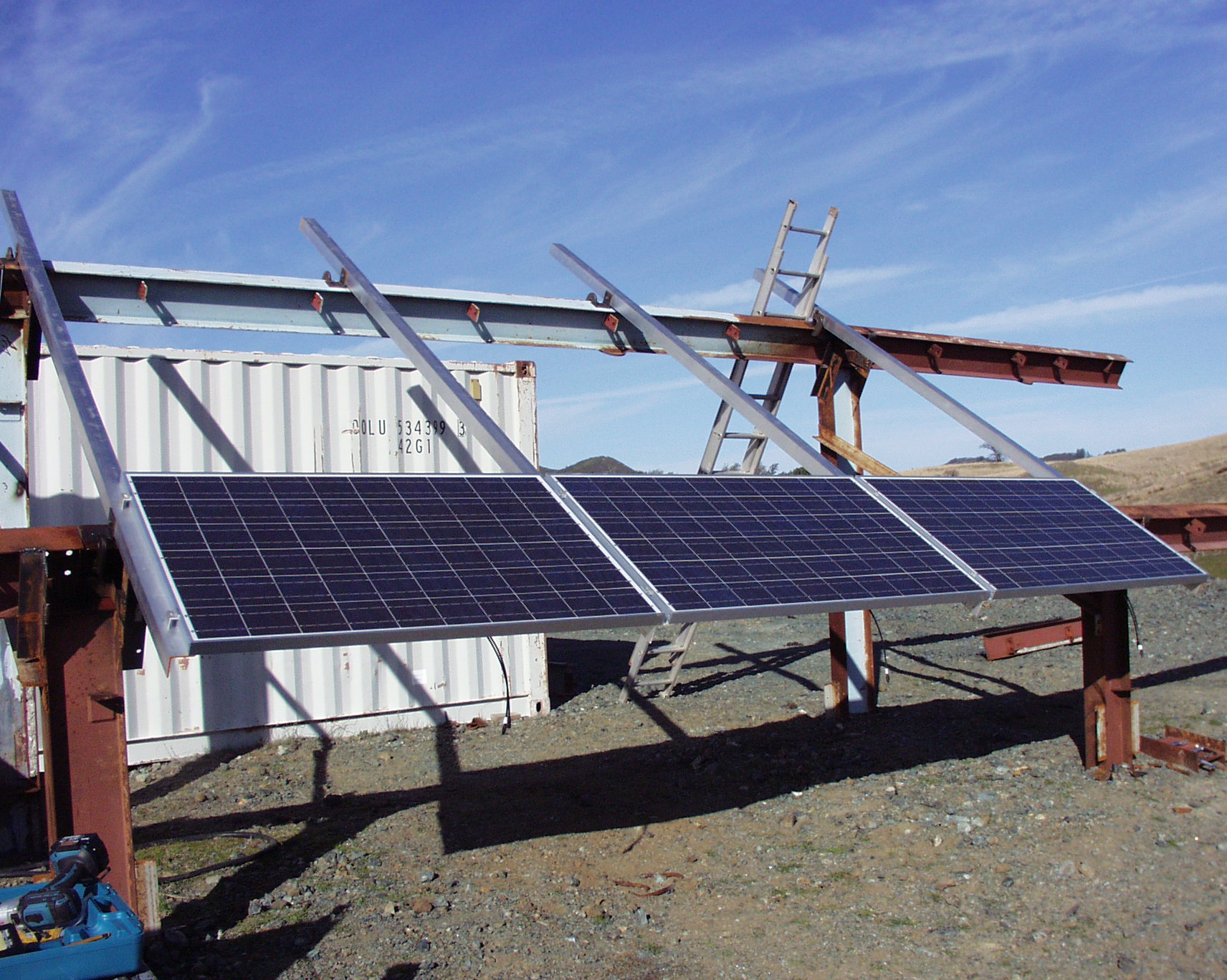
Runners and PV Panels Started
My runners are aluminum angle. Here a few PV panels have been installed. There will be a total of 33 panels, each of which is a 200 watt unit.

Cross Brace
If I put a force on the horizontal beams, I noticed a significant deflection way down at the other end. The structure also had a resonance with a periodic force at the same place. The fix was a cross brace which stopped the deflection and the resonance. It was so effective in stiffening the entire structure, that I didn't need one at the other end. The piece of blue channel is oversize for the application, but I have lots of it. The green Onan diesel 20 kW generator in the background is for powering the arc welder.
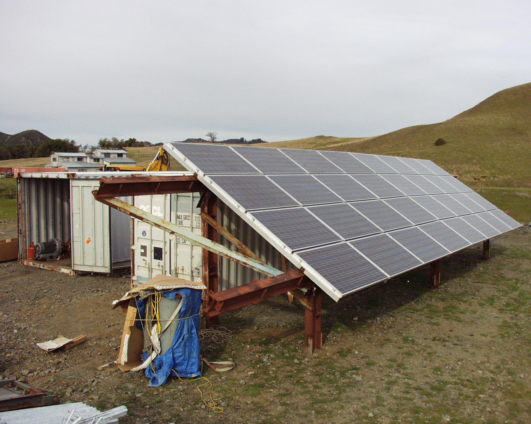
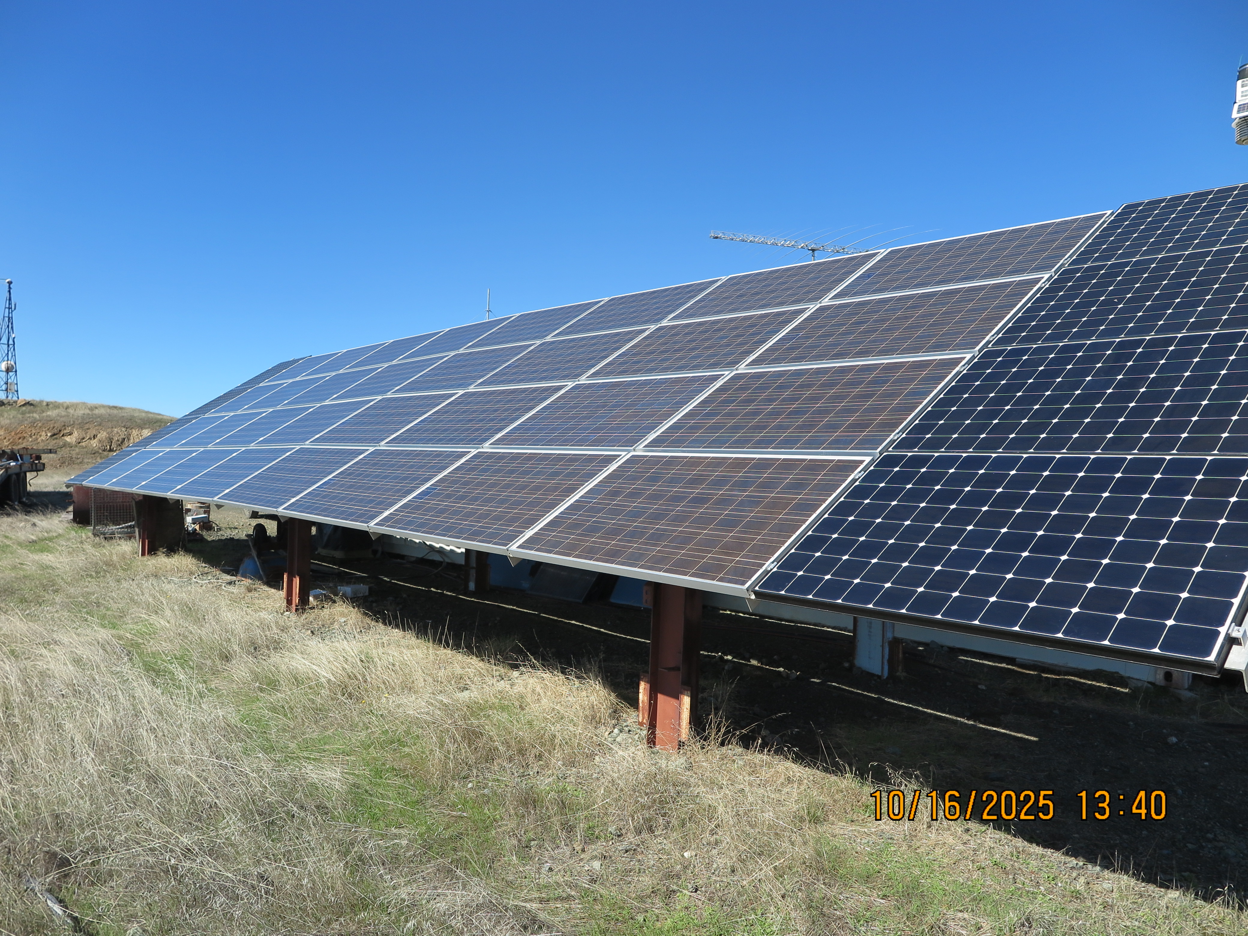
Completed Array Minus One
Here is the completed array, minus one PV panel which is to go in at the far east end of this picture. The gaps are for future expansion; one column at the near end, and another at the far end.
So far as of February 2015, I've had a maximum wind gust of 83 MPH with sustained wind of 52 MPH, and have no damage to the array. In that same storm with the 83 MPH gust, I have a neighbor whose array was bent into a pretzel, so I'm glad that I overbuilt mine. Note the fine weather protection on the old Harnischfeger arc welder.
On 13 January 2023, I had a 101 MPH gust which I'm happy to say, the solar array survived. Many pepperwood trees around the mountain top didn't.
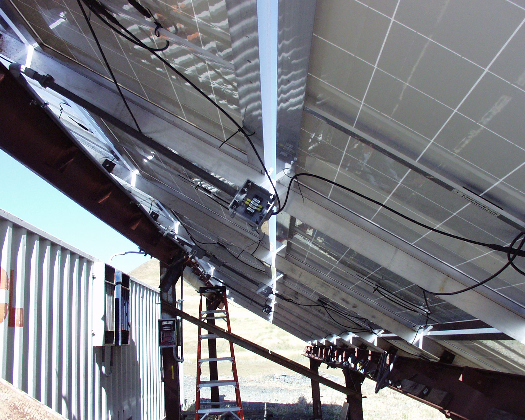
Wiring PV Panels
Here is the underside of the PV array. I am in the process of wiring the cells. Each string is three cells in series, and two of those in parallel. That gives about 14 amps at 95 VDC or so. The entrance to the container has two combined strings which I am calling Zone 1 and Zone 2 of 95 VDC at around 45 amps each in full sun.
A note about the enclosures on the side of the container: I knew all the electronics going into the container would generate tons of RFI due to the fast edges of switching devices, and so I elected to filter every cable entering or exiting the container. Those two enclosures contain the filters handling the DC from the PV array entering the container. Each filter will handle 25 amps from DC up through 60 Hz, so I have paralleled a pair for each zone in order to filter the + and - of the PV's DC. Later on, I'll be adding more filter boxes for the AC exiting the ISO container.
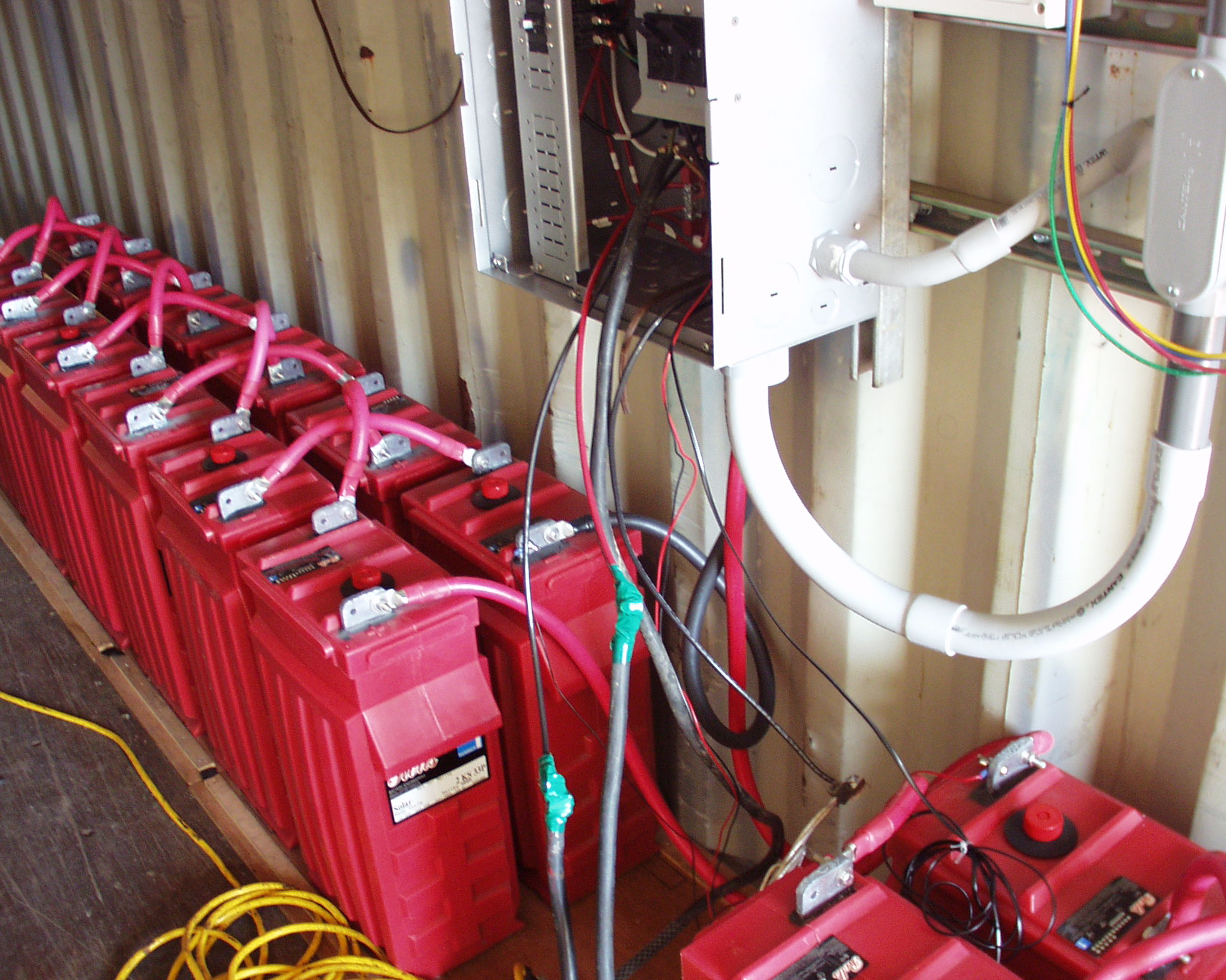
Battery Array
The 48 VDC battery array is made from 24 Surrette 2 volt cells, each with an amp hour rating of 1760 AH. They are wired in a crisscross pattern to minimize the inductance.

Apollo T80 Chargers
I purchased Apollo T80 charge controllers to charge the batteries. If I were beginning again, I would purchase Outback chargers rather than this brand. For one thing, they generate enormous RFI which at this point, I'm not sure how I'll attenuate.
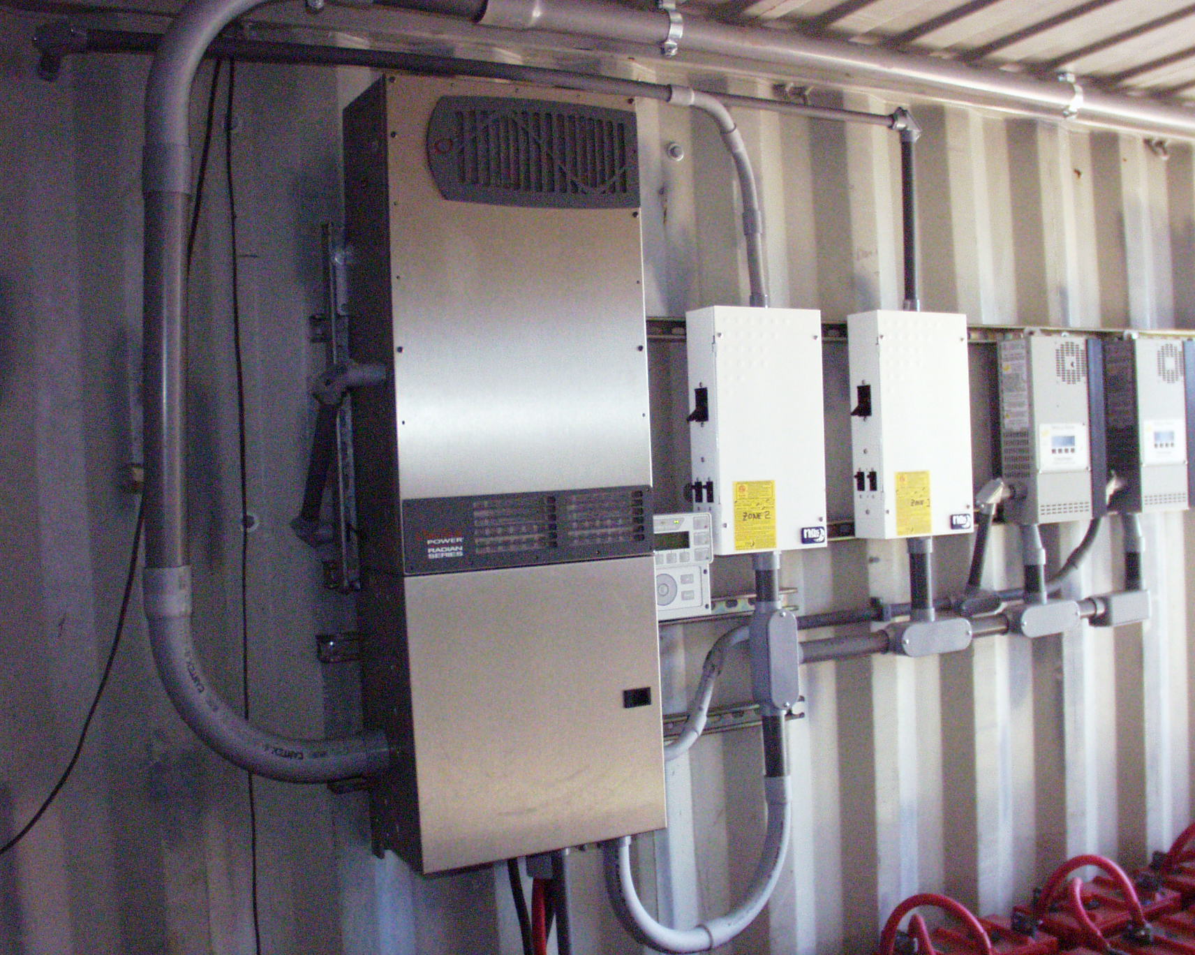
Outback 8000 Watt Inverter
The inverter is an Outback product which contains two 4000 watt inverters, each producing 120 VAC for the combined single-phase 120-0-120 VAC power source. I have not had a failure with this inverter, and so far, it has run 18 months without missing a single cycle that I know of.
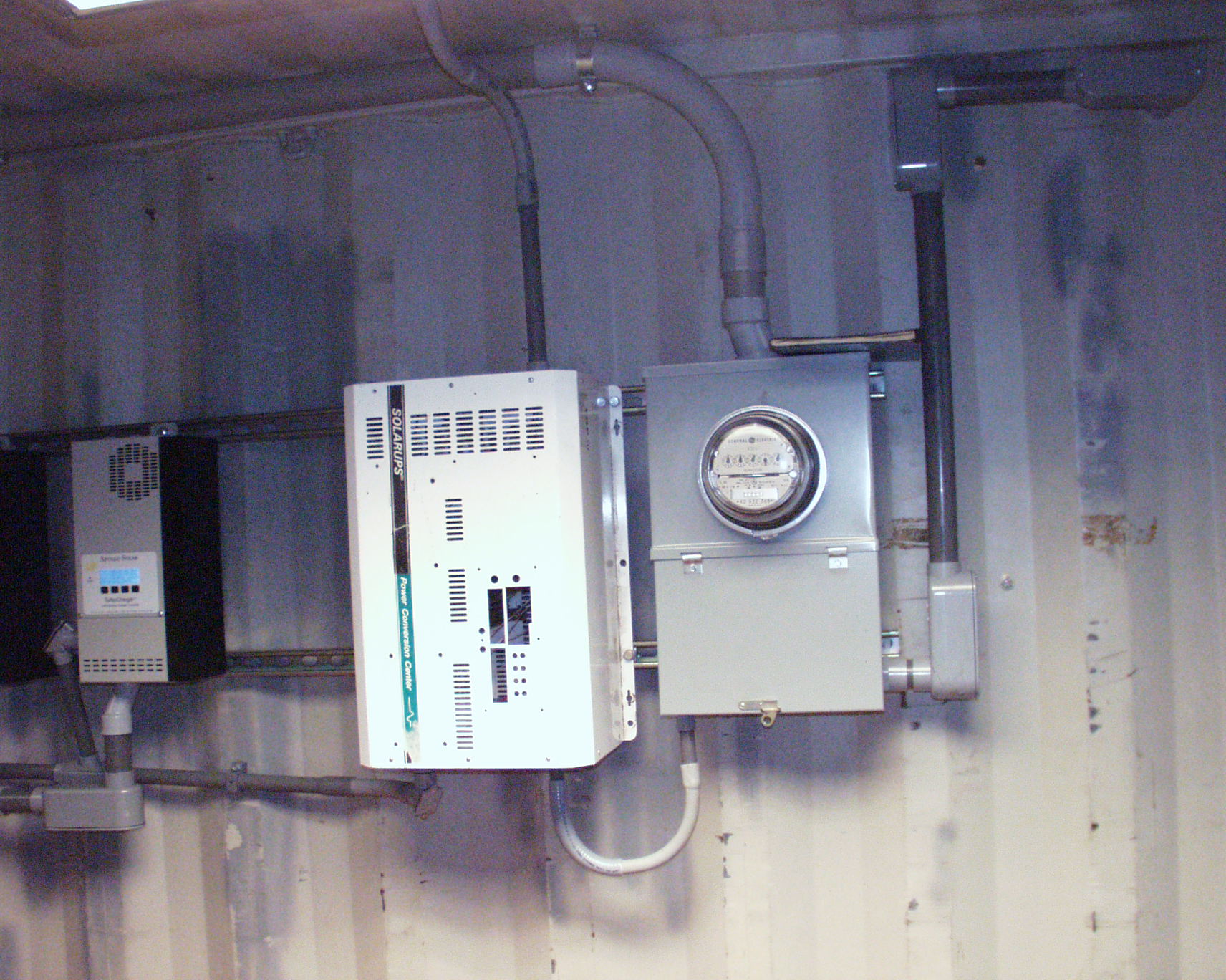
Watt Hour Meter
I meter the total energy in an old-fashioned watt-hour meter. Since it is a mechanical device, I never worry about losing data to a semiconductor or battery. The white old inverter box on its side, contains the monitoring and alarm electronics which interfaces with the monitoring computer at the far end of the ISO container.
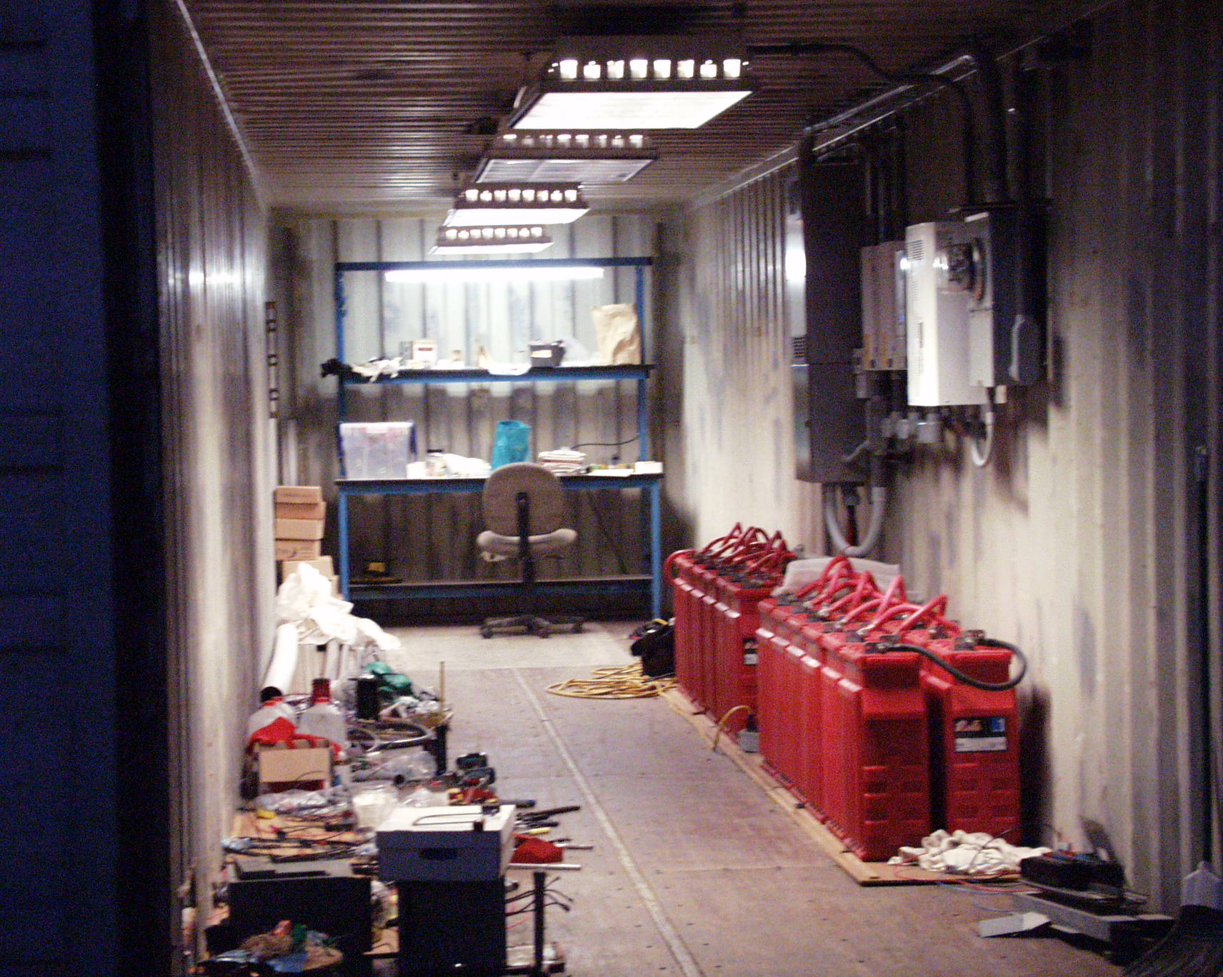
End View of Completed Solar Plant
Here is a view at night looking into the container with the completed solar plant. I placed a workbench with the computer under it at the far end which makes a slick office. I also installed light fixtures along the ceiling to complete the project.
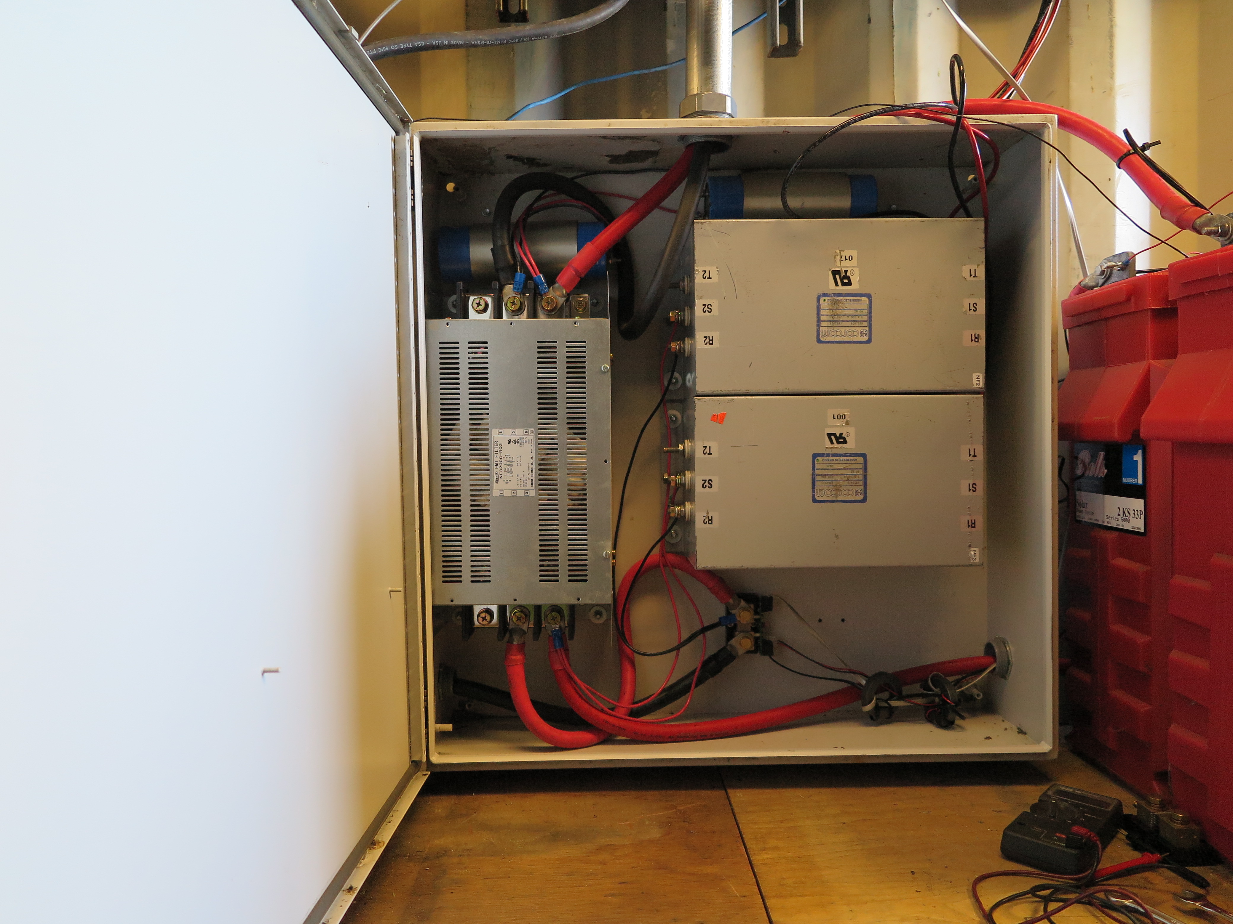
Filter Box
Oh no!!! I had just assumed the 40 foot container was steel all around. Of course I knew the floor was marine plywood, but I assumed under it was a steel skin. Not so! All the RFI I had hoped would be trapped in the steel Faraday shield, was pouring out through the floor!
To remedy that, I have installed this box with a 250 Amp common mode filter on the left, and two 100 Amp filters for the PV battery charger on the right. The 250 Amp filter is between the inverter and the battery. The blue electrolytics along the top are to mitigate the inductance the inverter sees because of the common mode filter. They are two 15,000 uFd, 250 volt, low ESR units from surplus equipment. The two 100 Amp units are between the charger output, and the battery. This keeps the battery all DC, and keeps the RFI producing high frequency crap back into the defective units producing it.
I also am going to all-metal conduit from the plastic stuff, and in addition, I am carpeting the entire floor with sheets of diamond plate aluminum. I have four sheets down as of this writing, and have noticed about a 10 dB decrease in the RFI from my solar system.

New Array Additions
Someone on Freecycle in Palo Alto offered 14 relativly new PV panels for free, so I jumped at the oppurtunity, drove over and took all 14. The new SunPower panels are the darker ones on either end of the array.
As luck would have it, 4 of the new panels in series is only 10 volts different than 8 of the old Sharp panels in series, so I rewired the entire array to accomodate that new configuration. My new loaded PV bus voltage is around 254 VDC. The old Sharp PV panels are 200 Watt devices and the new SunPower panels are around 350 Watts. My total array has gone from around 6 kW, to around 12 kW.
New Array Additions
Here is a view of the new array from the right. In the background is my LP-1005AA log periodic HAM antenna.
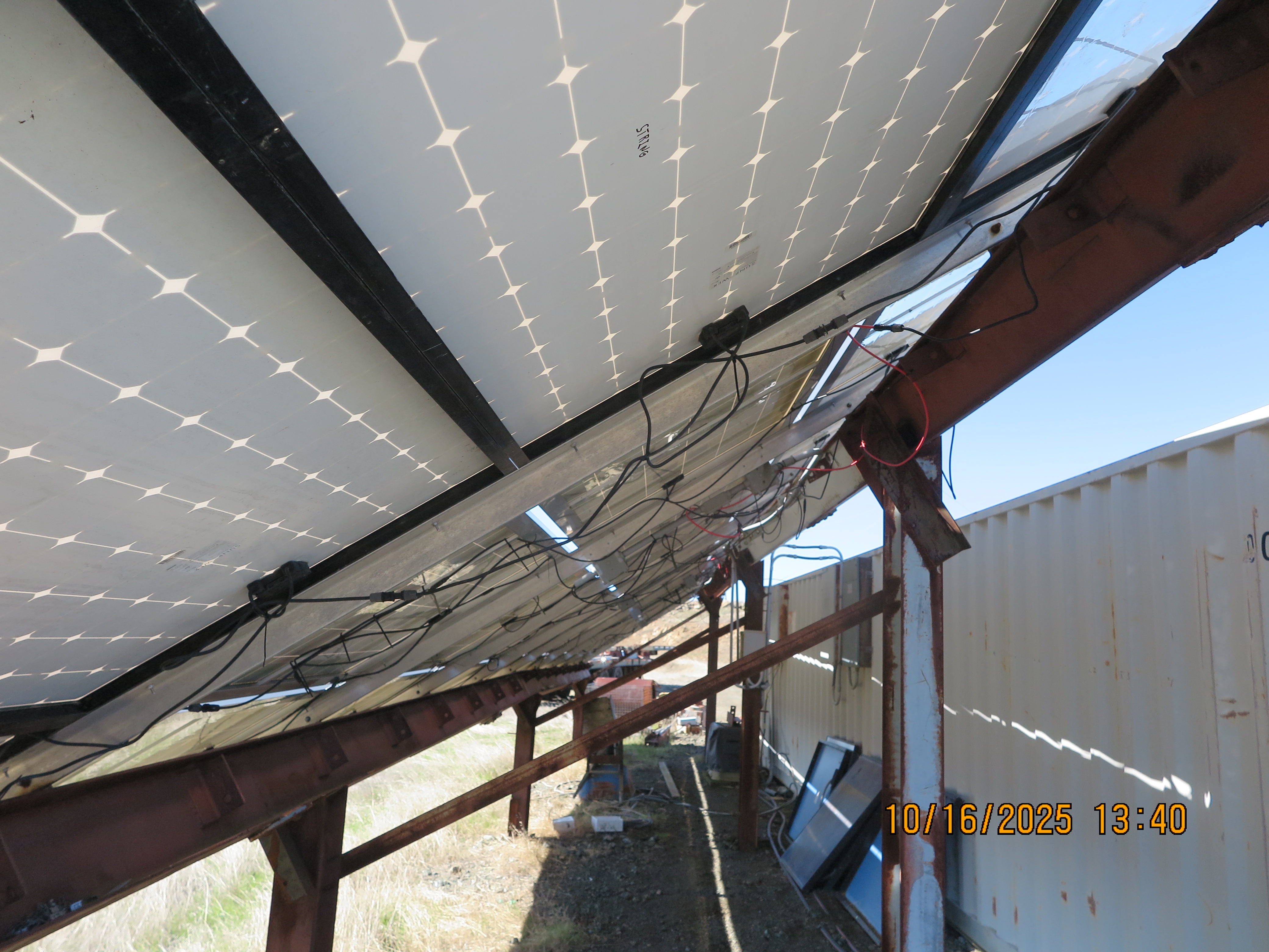
New Underside View
My backside wiring is not a pretty sight, but the cables are high enough off the earth to prevent the deer from chewing on them as has happened before.