Home phone: (408) 749-8522
e-mail: doug@dougronald.com
LP-1005AA
The US Antenna Products LP-1005AA is a log periodic antenna, horizontally polarized, on a twin tower support structure that places the antenna at 100 feet above ground level. This antenna is usually sold to governments, but I wanted a non-resonant antenna not requiring tuning over the HF bandwidth with some decent gain. This antenna has about 7 dBd gain from 3.8 MHz through 30 MHz and a 2:1 VSWR or better over the same bandwidth. It can handle 25 kW CW, so amateur use is a piece of cake. The following web page documents getting this large antenna on the air.
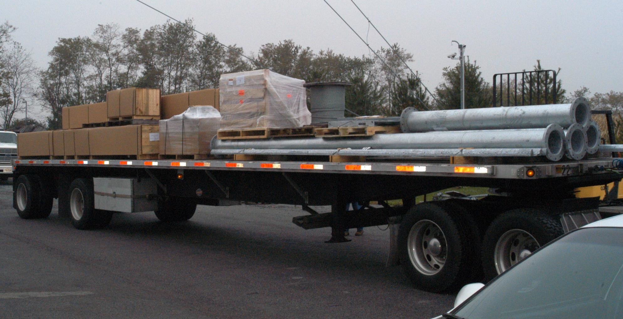
LP-1005 as shipped from the factory
The antenna and tower were packed on one 48' flatbed trailer for the trip from the east coast to the left coast where I live.
The tubes are the mast. The rotator is located in a cradle between the twin towers at the base, and the mast sits between the towers, supporting the antenna over the length of the tower.
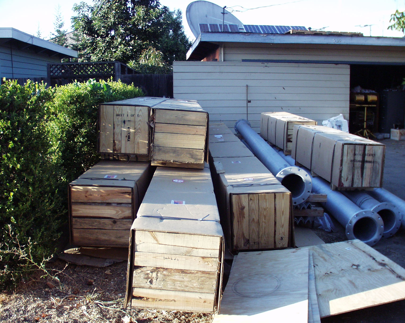
Most of LP-1005 unloaded to my side yard
Using my forklift, which I hide in the garage to avoid nuisance complaints from the city, I successfully unloaded the 48' flatbed. The garage door is off, because the forklift won't fit under the door.
The remainder of the antenna system wound up in the back yard. I would have placed all of it in the back but there was no way to get the long boxes and tubes past the house.
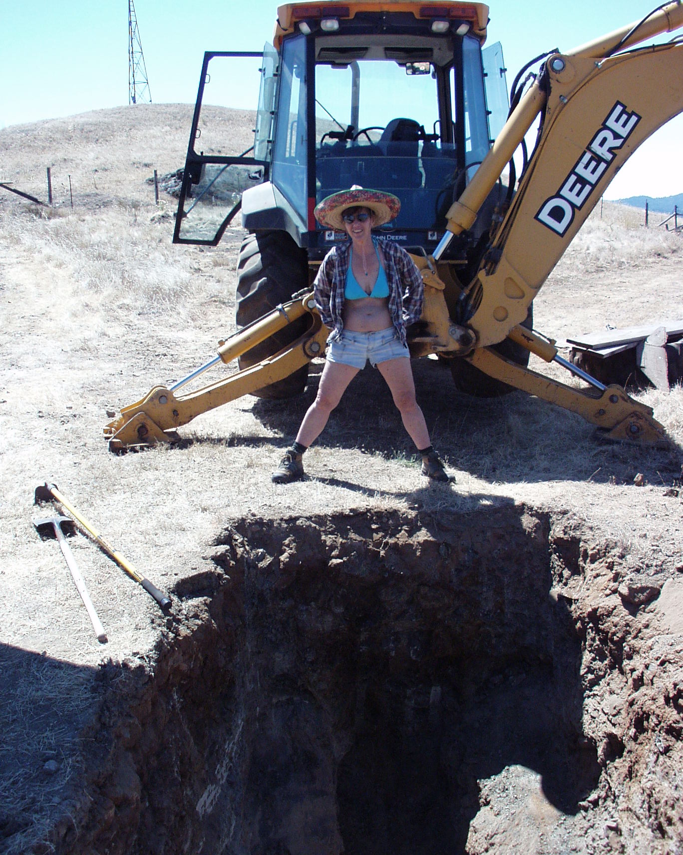
Twin Tower Foundation Hole
Using my Deere 410G backhoe, I dug the twin tower foundation hole and the four guy anchor holes. Standing proud over the dig-out is the XYL, Kristin.
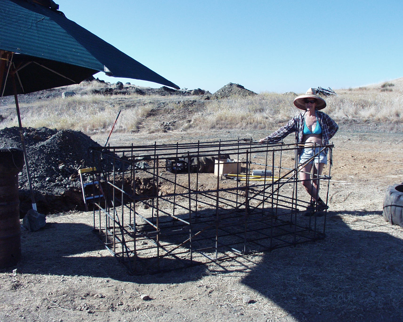
Twin Tower Rebar Cage
This is the subterranean rebar cage for the twin towers about 3/4's constructed.
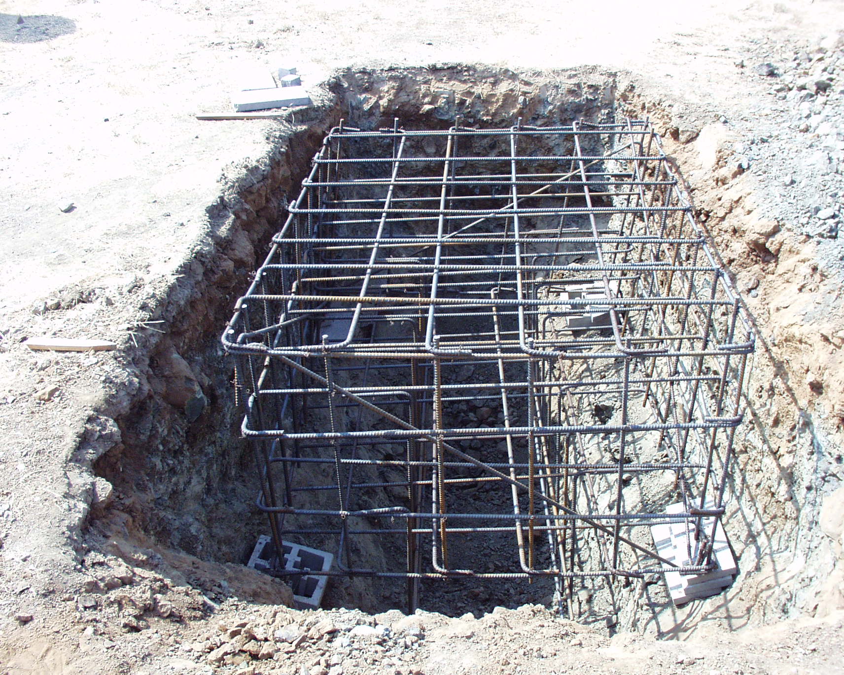
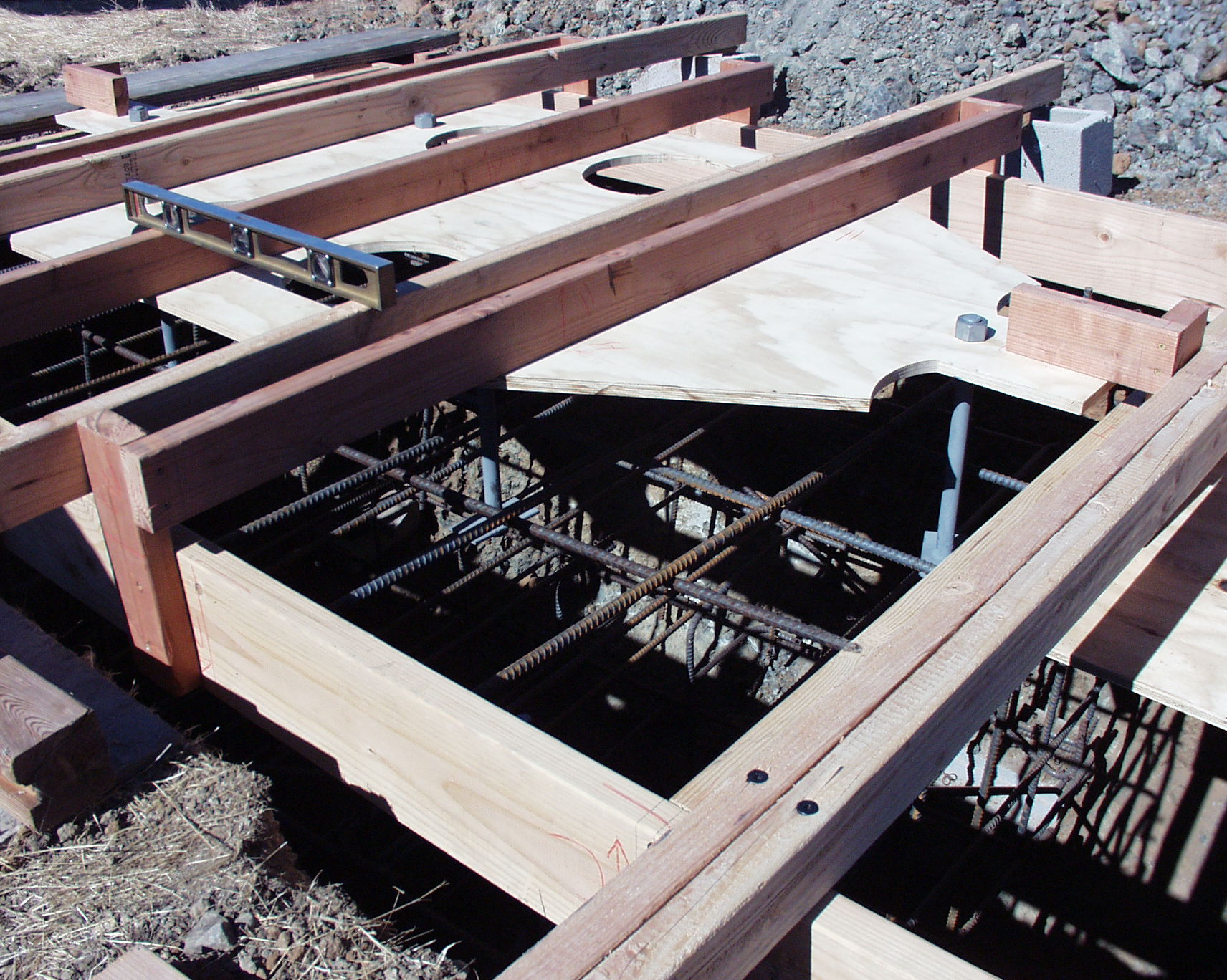
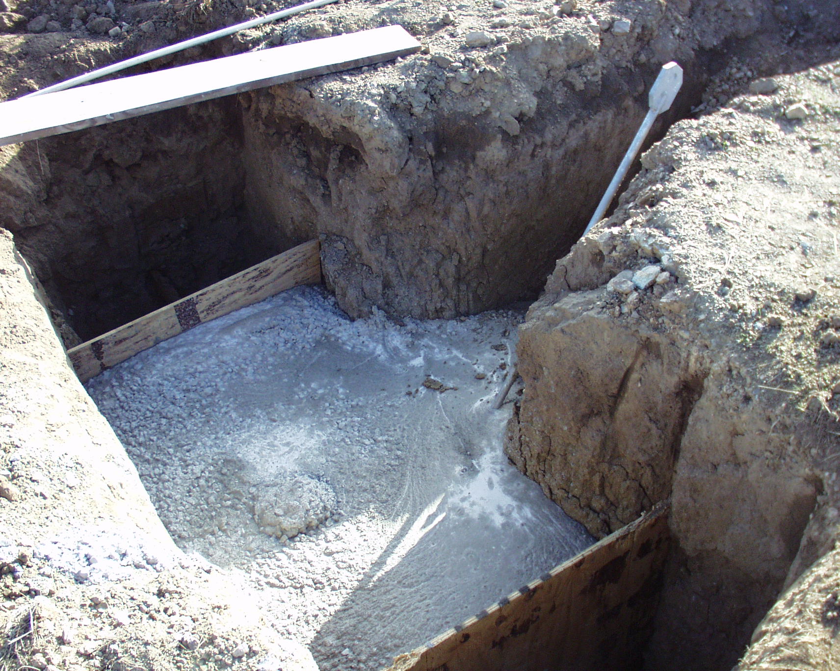
Foundation Rebar Cage in Situ
The rebar cage is in the foundation hole ready for forming-up the top plate. The plywood top plate will hold the six anchor bolts in fixed position for the cement pour.
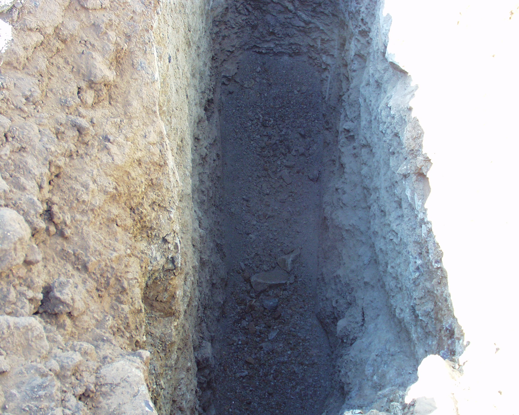
Guy Anchor Hole
There are 4 guy anchors. This is the hole for one of them in which a rebar cage gets lowered with the galvanized steel anchor attached. The hole is 5' deep as per the county approved plans.
Tower Base Before Cement
The complete twin tower base before the cement arrives. I also had all 4 guy anchors ready for the pour as well.
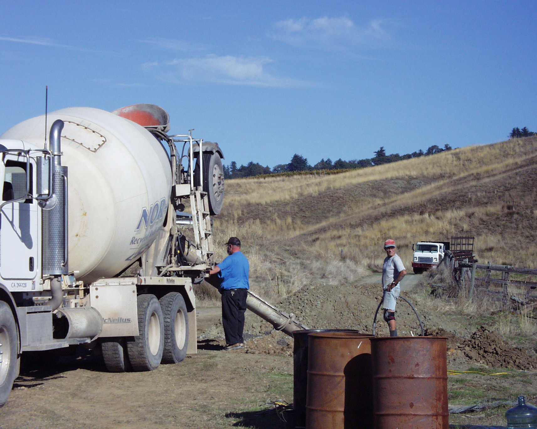
Cement Pour in Guy Anchor
This was the 5th cement transit truck, and the final pour which was the last of the four guy anchor holes. After consolidating the main foundation, consolidating the guy anchor holes, and smoothing the twin tower foundation top, I was tired.
Guy Anchor Pour
One of the four tower guy anchors after the pour. There is enough concrete in the foundation to break the anchor rod before that block of concrete will budge.
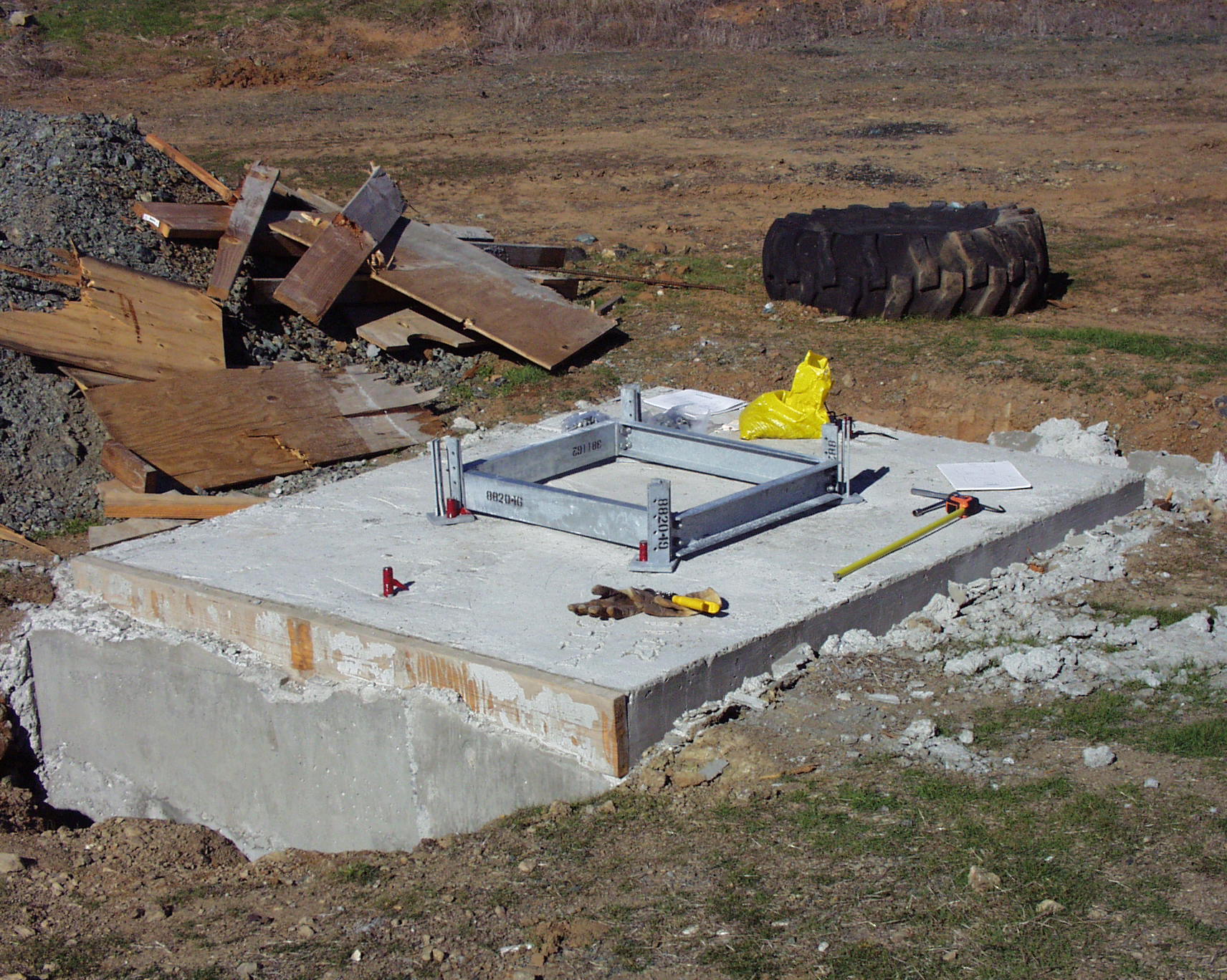
Twin Tower Foundation with Base
I was anxious to see after I stripped off the formwork if the base would fit. I had some movement during the pour of the template, but because the manufacturer machined slots rather than just punching holes for the anchor bolts, everything fit.
I know the foundation isn't pretty, but I was very tired after the day of pouring, and just didn't have the energy to smooth it off. If I were to do it again, I would pour the twin tower foundation on the first day, and save the guy anchor pour for another day.
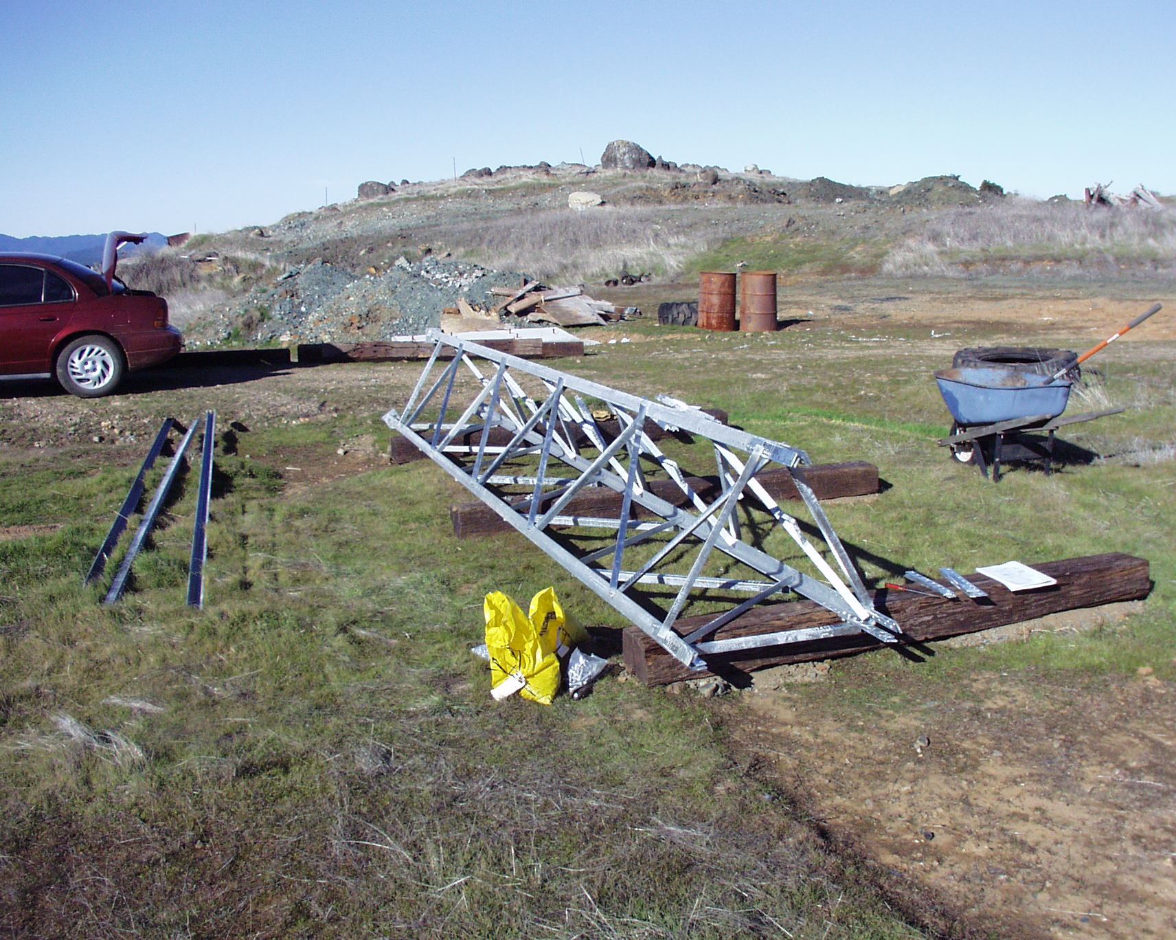
First Assembled Tower Section
There are 8 of these to assemble and there are a lot of bolts in each one, but I was really happy to have finished the first one. Each section weighs about 450 pounds.
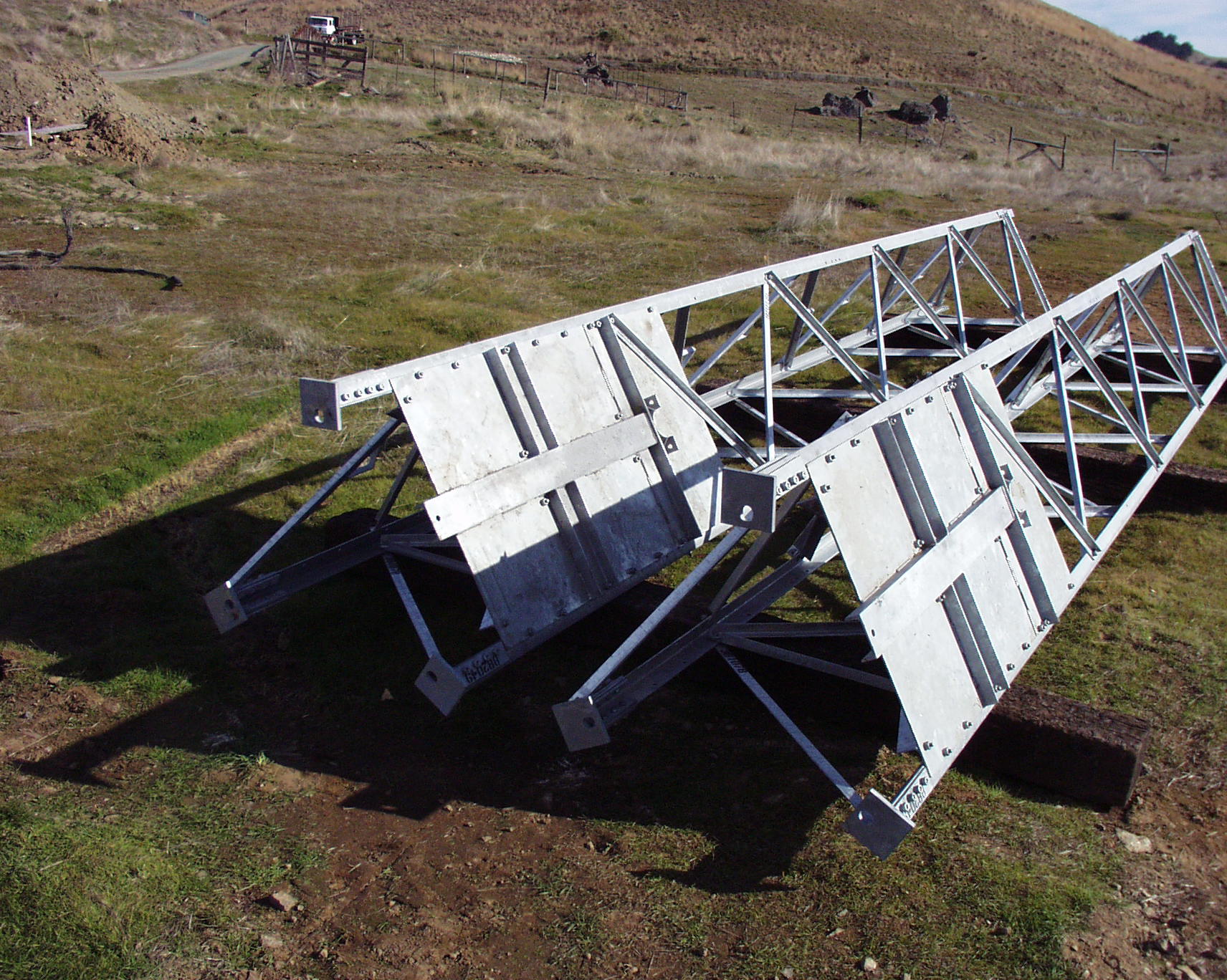
Finished Two Bottom Sections
I have completed constructing the left and right bottom tower sections. The two heavy plates face each other in the final configuration with the rotor in between them.
Bottom Two Sections on Foundation
Just to see how everything was going to fit together, I put up the bottom two tower sections on the foundation. The tops didn't align very well because the foundation surface was not leveled to perfection. I knew that later in the process I could true the tower after the guys were installed. I would be able to shim any of the base plates that had gaps.
The crane truck has come in very handy for a number of projects. The lifting capacity close-in is 20,000 pounds, and the reach is up to 42 feet. It will pickup 3300 pounds with the boom out at 30 feet. The truck is an International 9300 with a CAT 3406E engine.
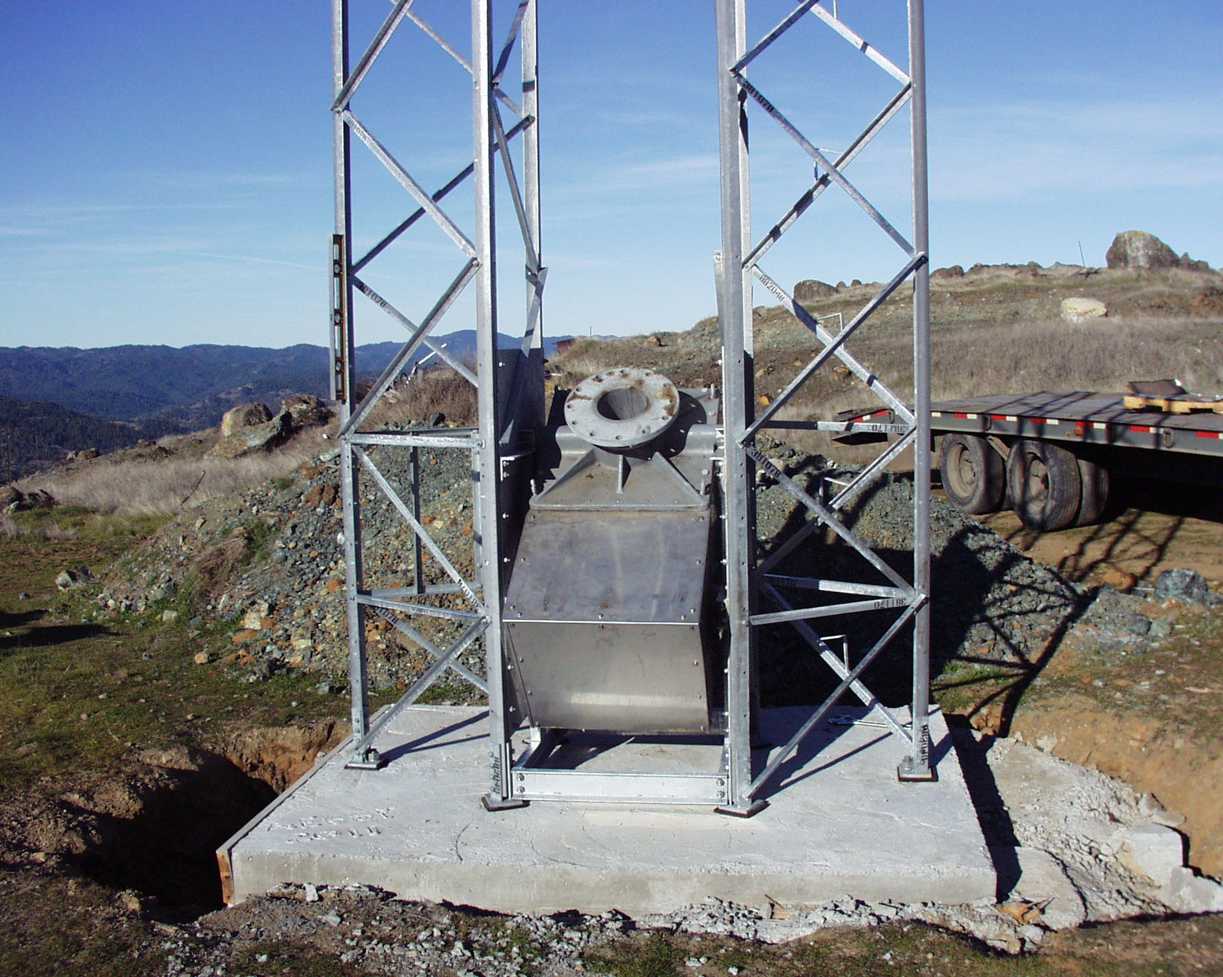
Rotor Installed in Base Cradle
The rotor will support 20,000 pounds of thrust, and rotates at 1/2 RPM. I'm not sure of its weight, but it is very heavy. There is a lot of cast iron in there. This is just a temporary install to see how the rotor would fit in the cradle. At this point, I dismounted the rotor, and towers from the base in order to join all the pre-assembled sections together.
Towers Fully Assembled
I have both towers completely assembled, and now have to join them together.
Joining Bases
I have the towers aligned face-to-face, and am now joining them with the supplied channels.

Joining Tower Tops
With a come-along, I'm aligning the tower faces, and securing the tops with the supplied channel connectors. Also, along the top is the pulley used for pulling the mast upright. This pulley extended from below one of the cross channel connectors.
Tower Base Alignment
I prepared a wood template which exactly fit over the already cast foundation bolt pattern. I used a come-along to get the two tower bases to exactly align with the template, and then torqued-down the channel bolts to lock the towers in place.
Tower Guy Install
I prepared the four guys each with four insulators. This took some time to cut the half-inch steel guy wires, thread the guy-grips, and then twist the guy-grips together. There are 10 guy-grips per guy line, for a total of 40 in the system. The insulators are necessary in the guys to break-up any resonances caused by the guy lines themselves, which would alter in a negative way, the radiation pattern.
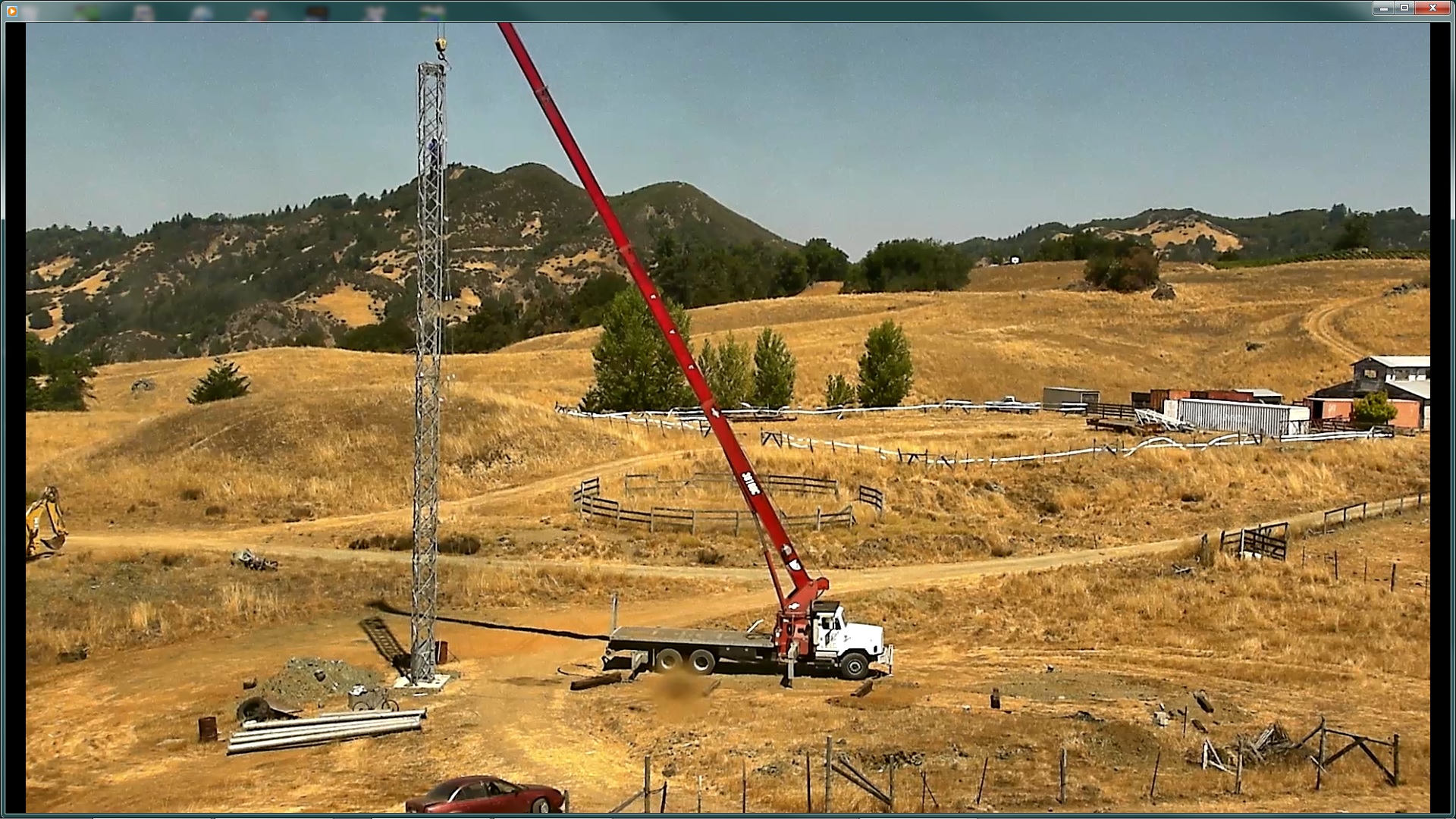
Lift With Towers at 45 Degrees
The crane truck with the towers at about 45 degrees. The towers mated together weigh about 3900 pounds. I hired the crane and operator from Daniel Steel in Ukiah to execute the lift. Devon Daniel is at the controls.
Twin Towers Upright
Everything is pretty straightforward here, I'm just hoping the base bolts line up.
Disconnecting the Crane Choker
I'm climbing near the top to get to the rigging in order to disconnect it. In the background you can see Grizzly Peak which at 2975 feet is my greatest obscura. My towers are sited at 2410 feet above average sea level. Thanks to the County of Mendocino California, the towers are sited in this depression, the only placement position they would approve for this size antenna. I would have preferred to site it up on the corral visible in the background.
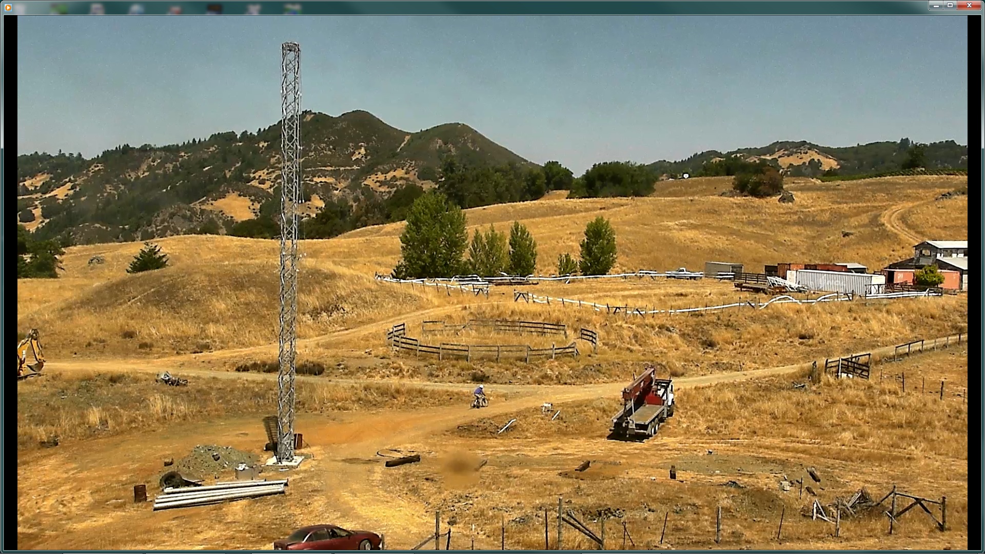
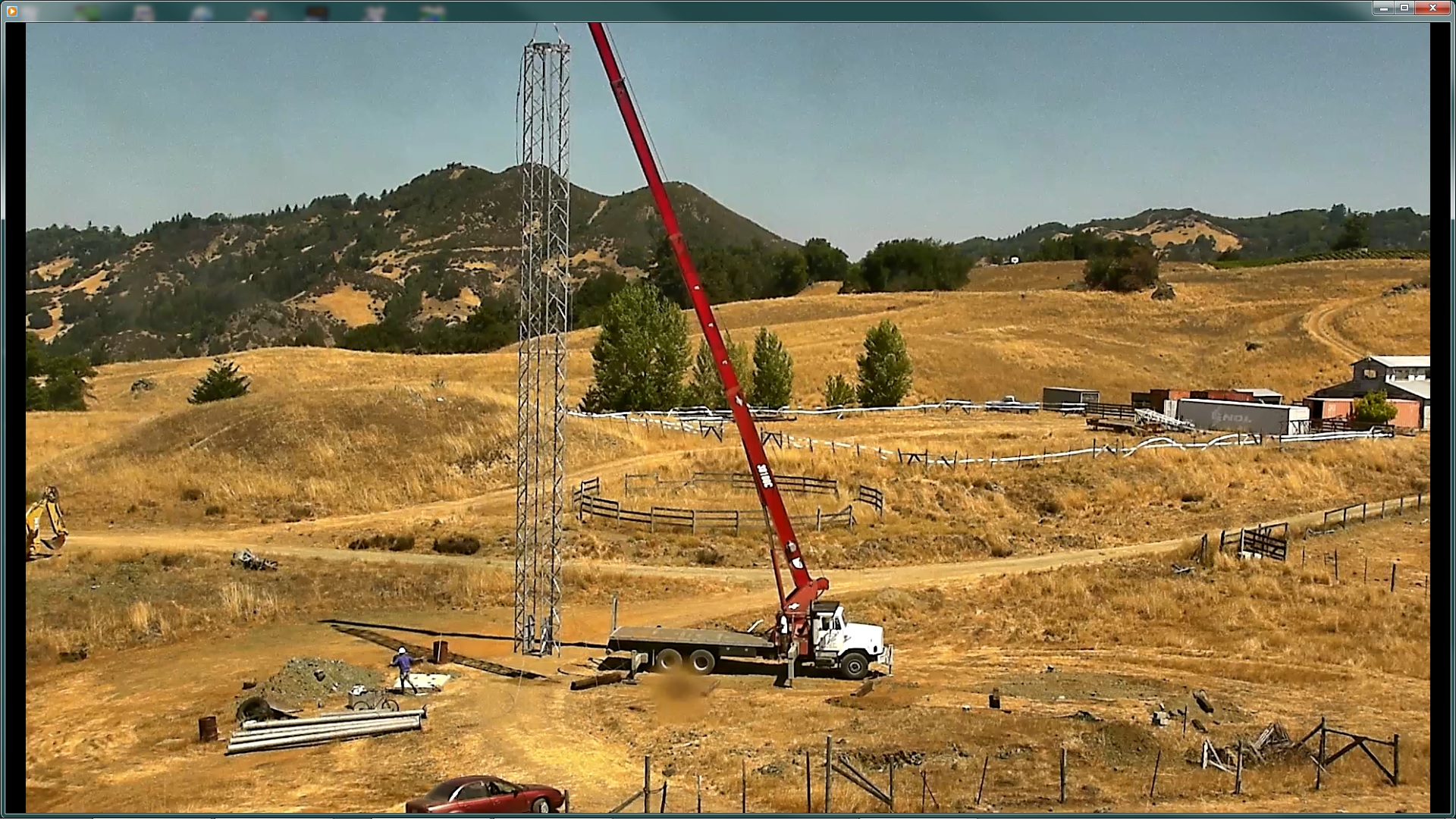
Twin Towers Up
The crane guy is headed back over the hill to Ukiah, and I'm headed back to the house on my bike for a cool drink. Note that the guys are not attached to the guy anchors. When I was at the top disconnecting the rigging from the crane, I tried to rock the towers back-and-forth, but they felt very stiff. Since this was summer, and the winds are more tame at this time of year, I felt safe leaving it unguyed for a couple days.
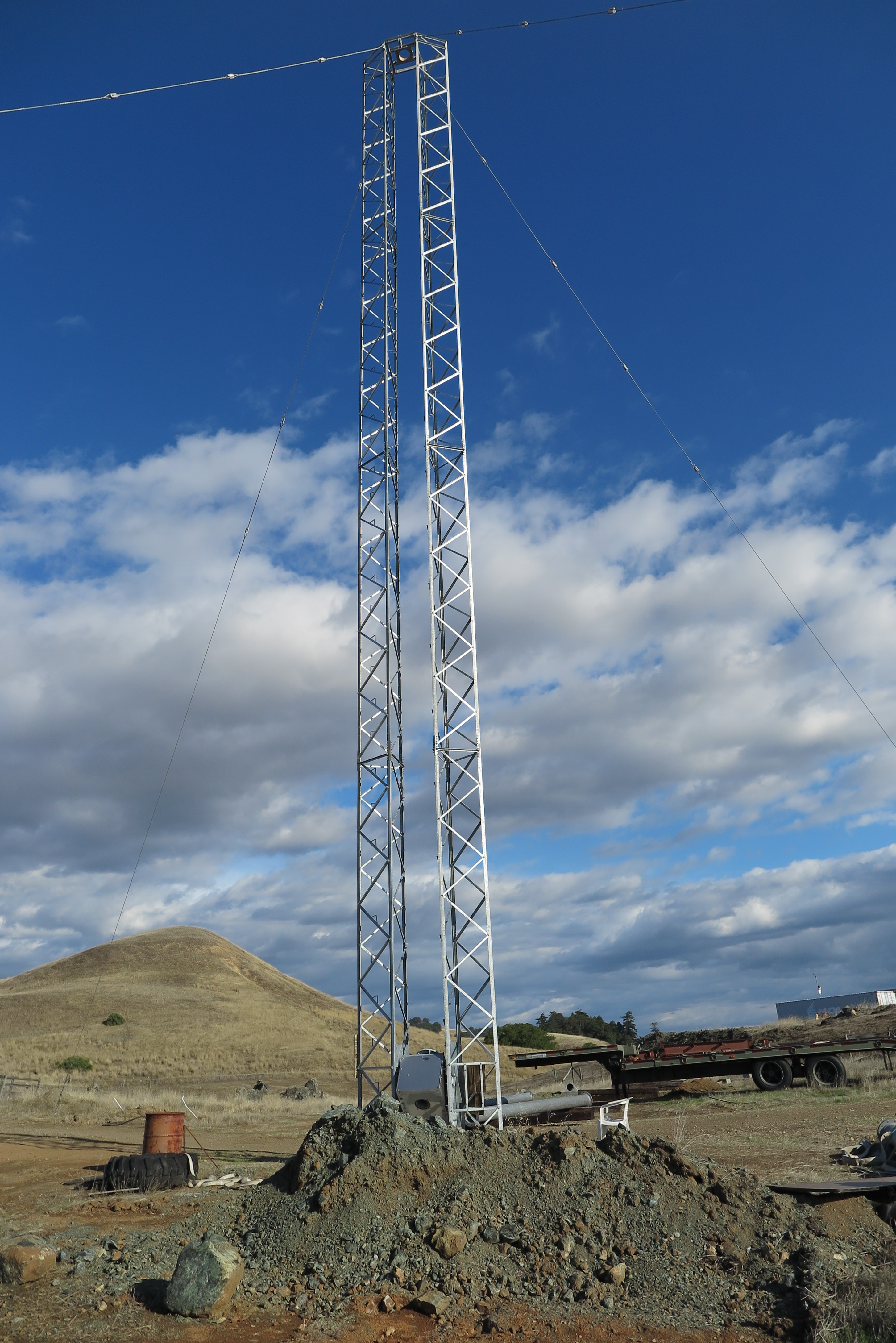
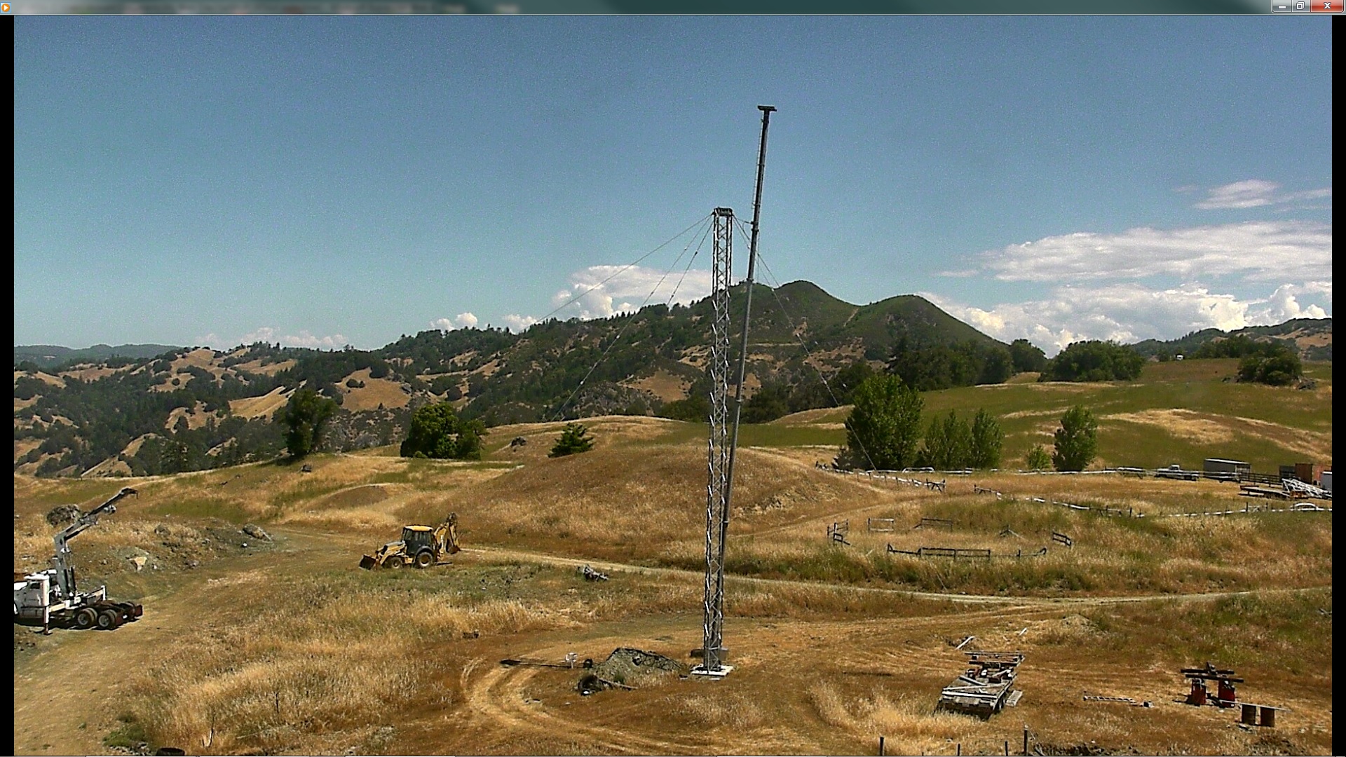
Twin Towers Installed and Guyed
The twin towers are 80 feet in length, but the mast will protrude from the top by another 20 feet to give a total height of the LPDA antenna of 100 feet.
From this view can be seen the insulators used to break any resonances in the guys which would effect the radiation pattern. The spacing from the top down is 8', 10', 10', 10', then another 70 feet or so to the guy anchors.
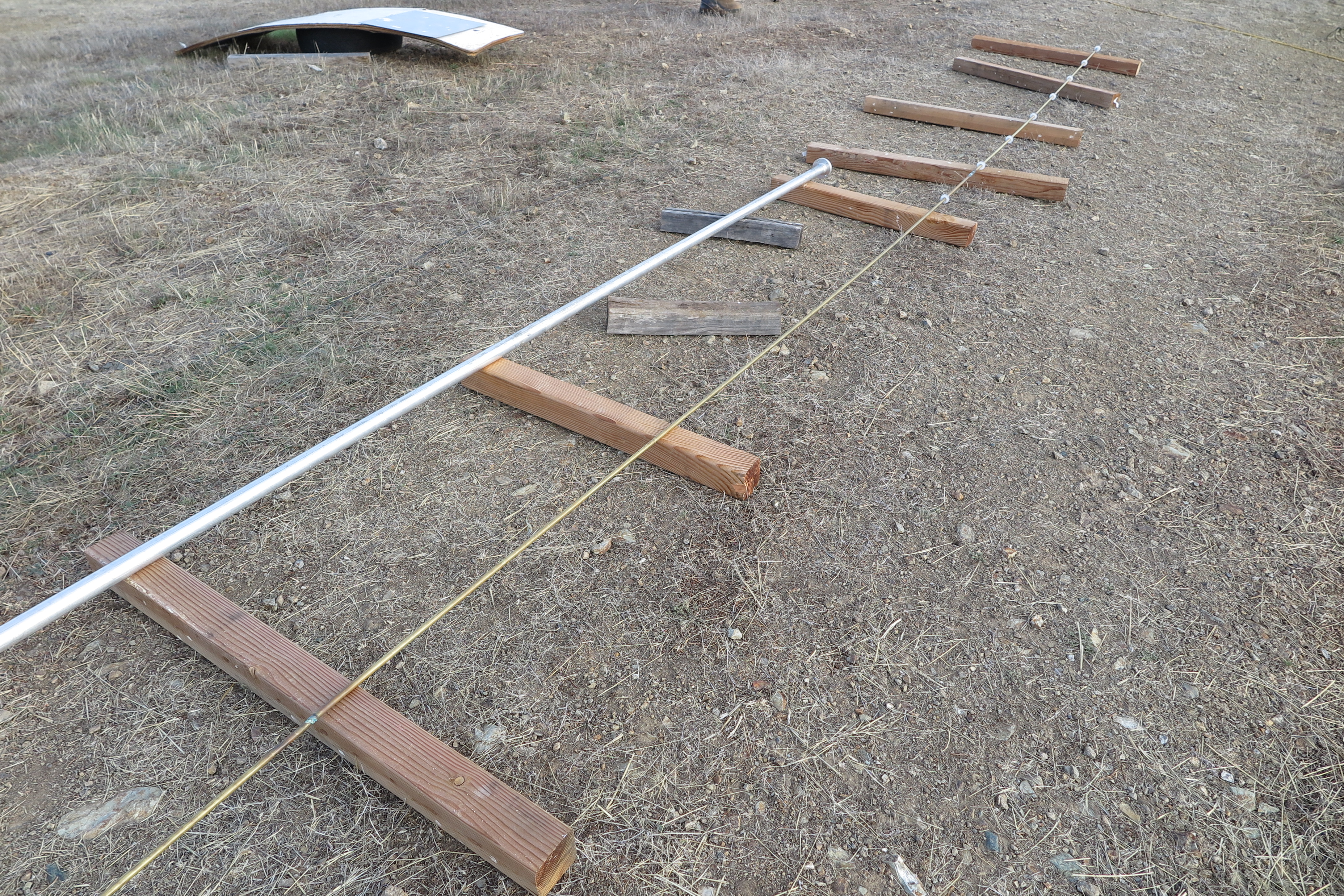
Mast Assembly
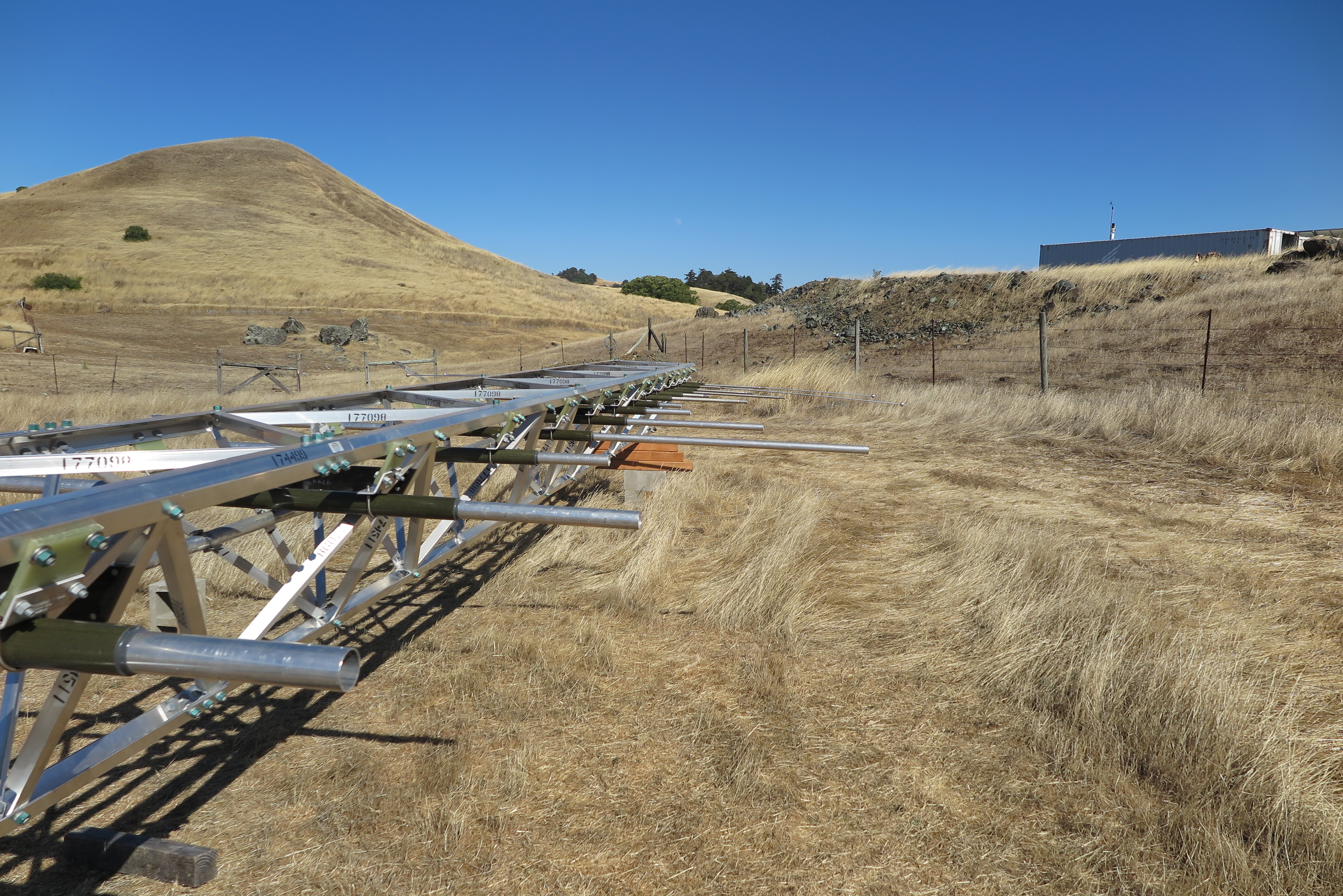
Most of the mast has been assembled now. Each of those tubes is about 1500 pounds. The bottom ones are schedule 40, but the top two are schedule 60. They are beefier because they protrude from the top of the twin towers, and have more bending moment on them.
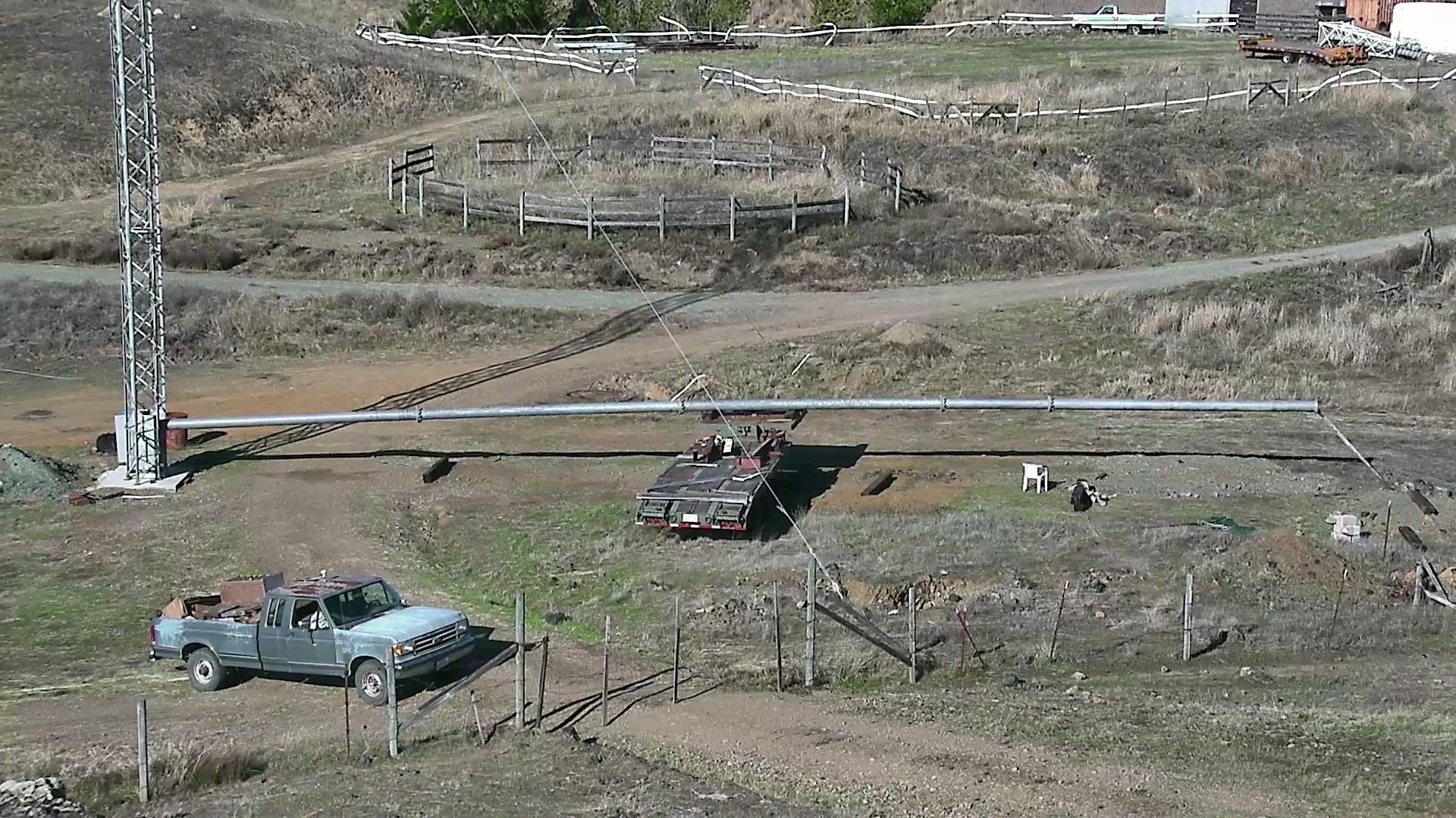
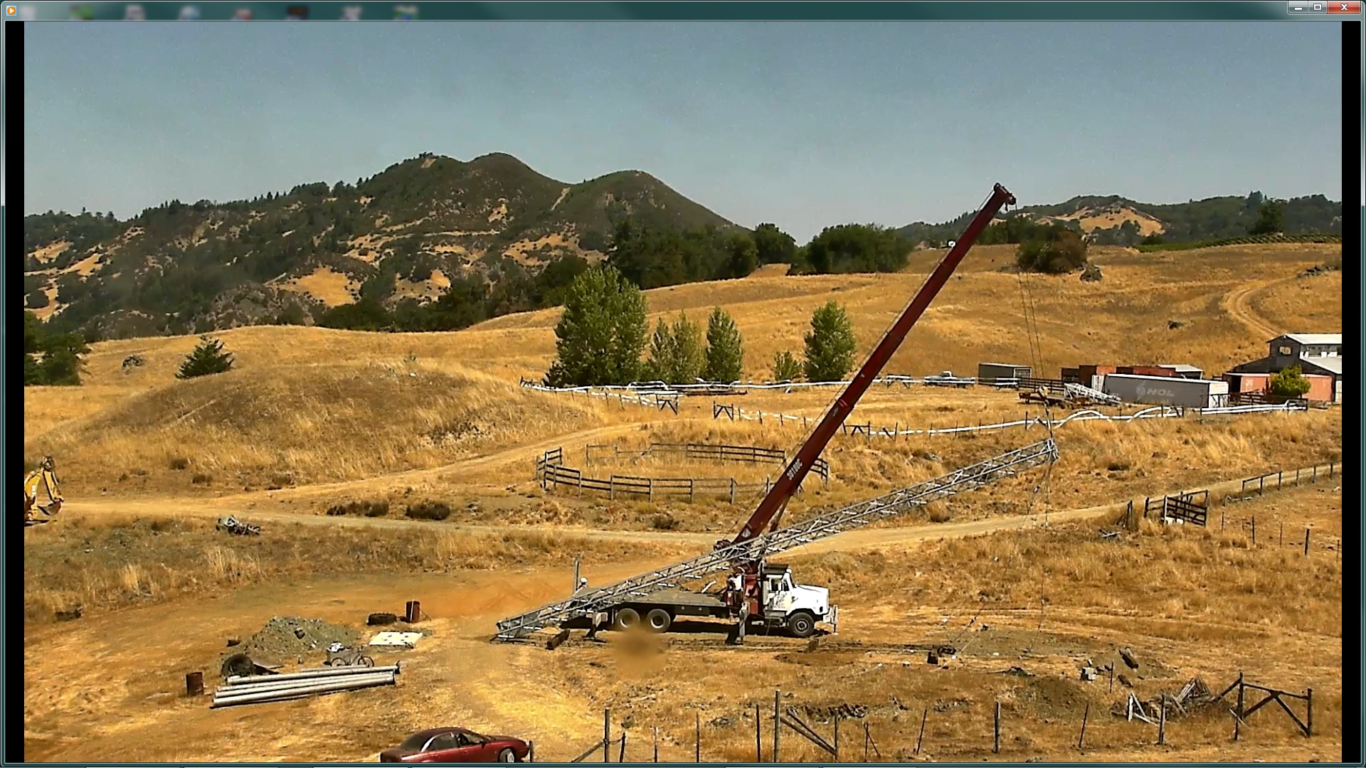
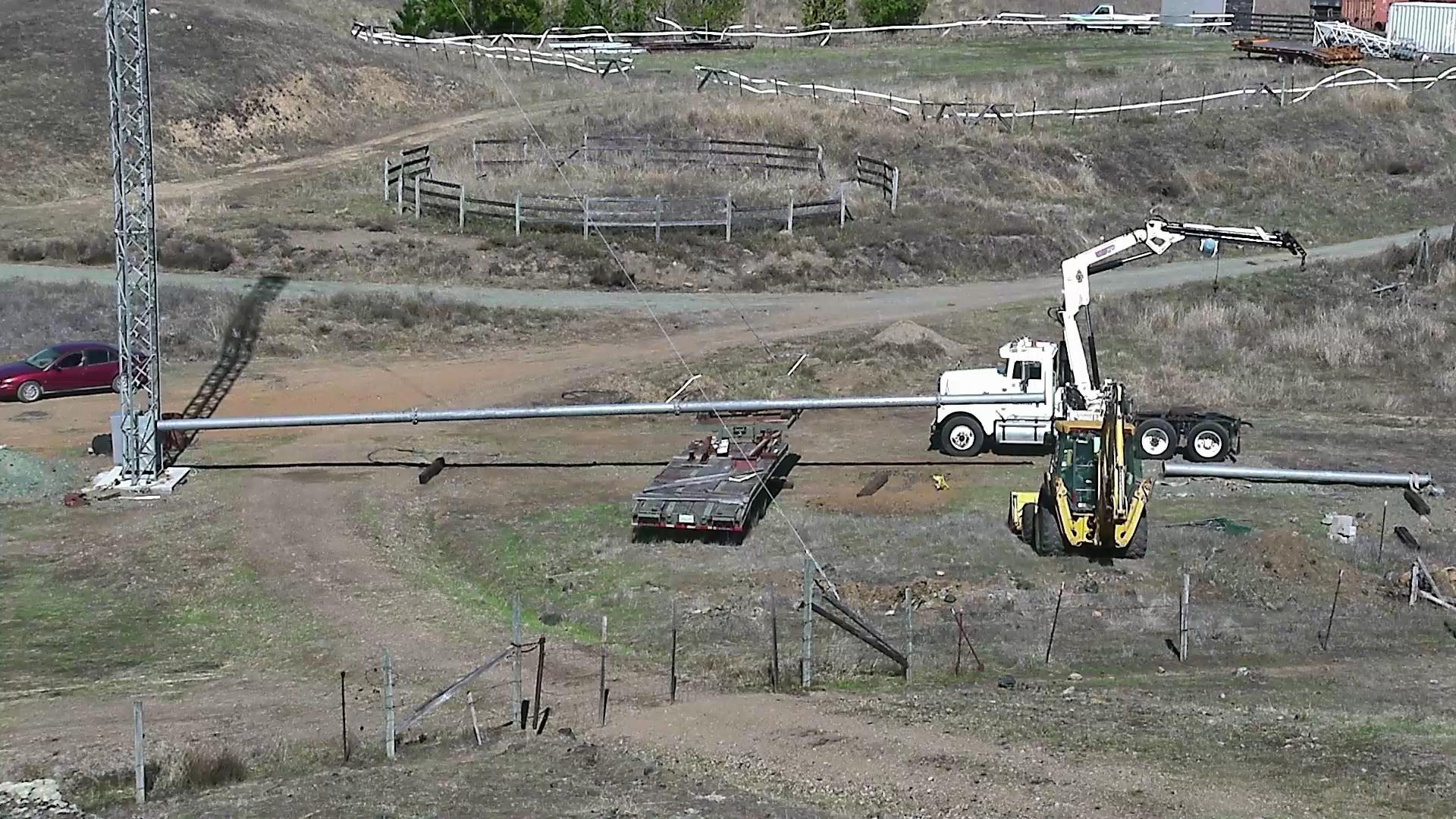
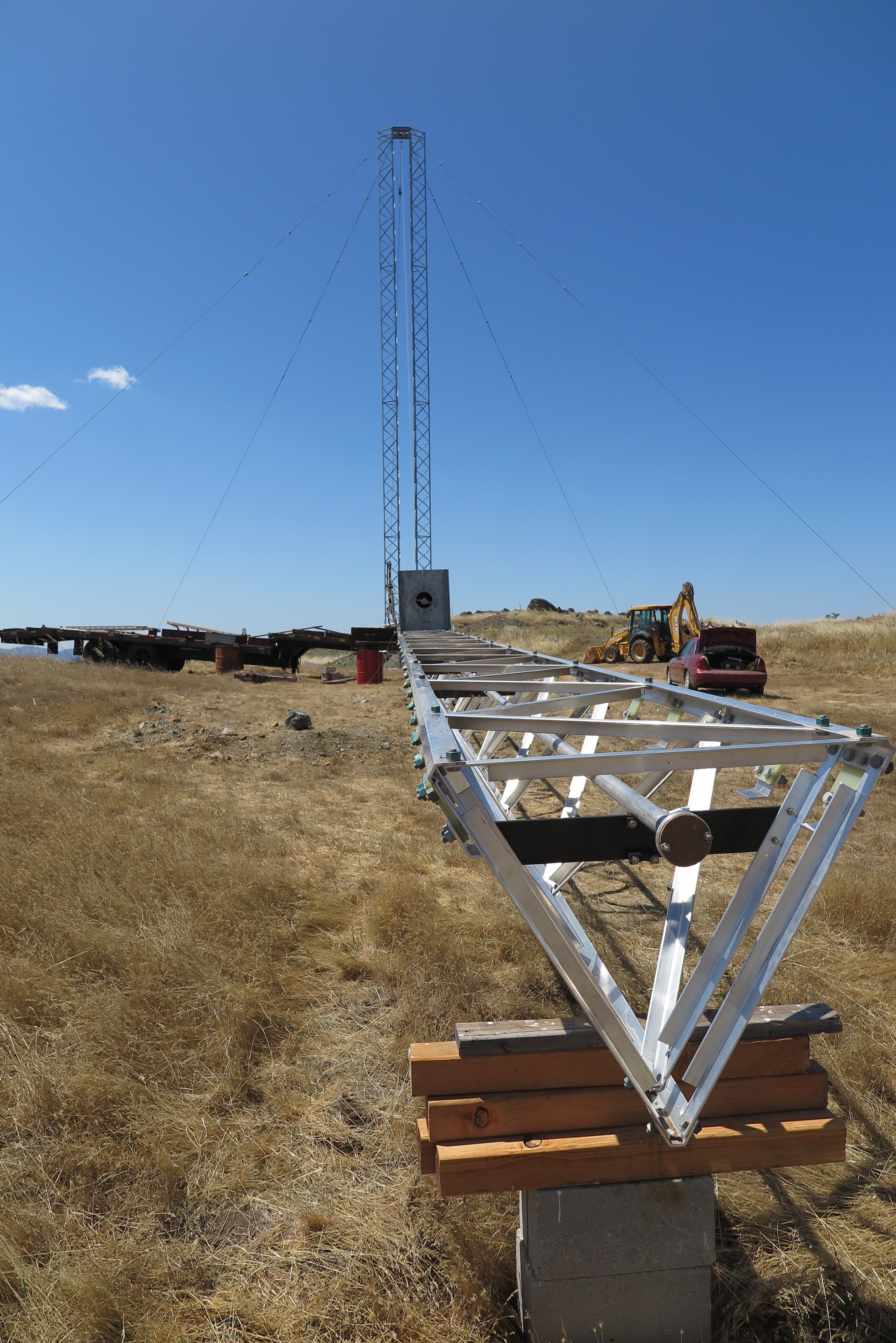
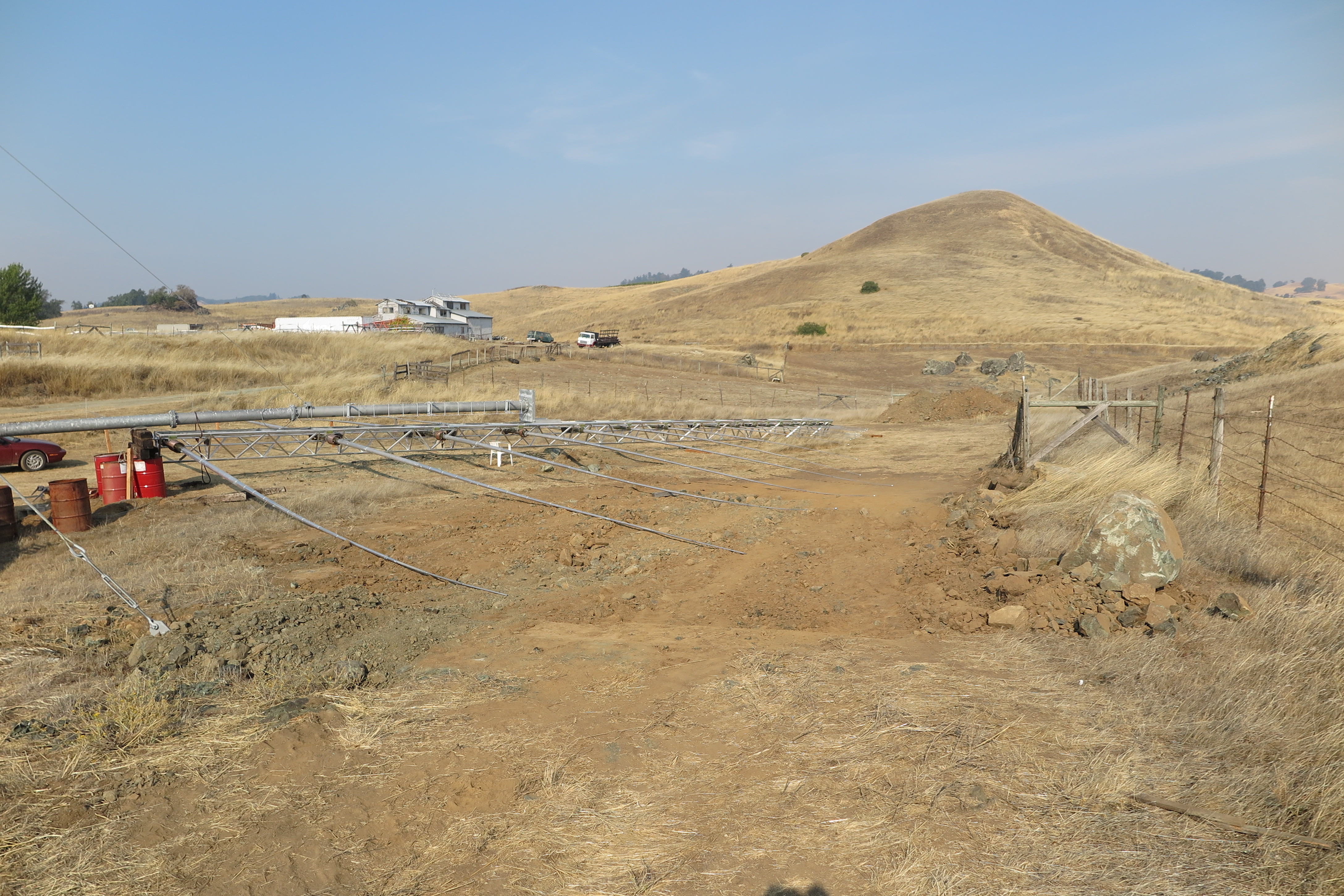
Mast Completed
I placed a flat bed trailer as far from the tower base as I could, and still have room beyond the trailer for the antenna assembly. After installing the last sections on the end of the mast, it deflected significantly, so I have now added four 55 gallon drums with railroad ties as a support. As I build-out the antenna, I'll use the wire rope which attaches near the top of the mast, and then goes up to the top of the tower where it loops over a pulley, and on down 90 feet back of the twin towers to a winch. I can raise and lower the mast to facilitate assembly of the antenna. That assembly is scheduled for the summer of 2015.

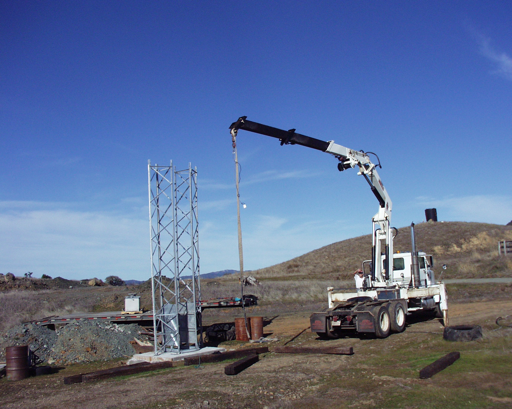
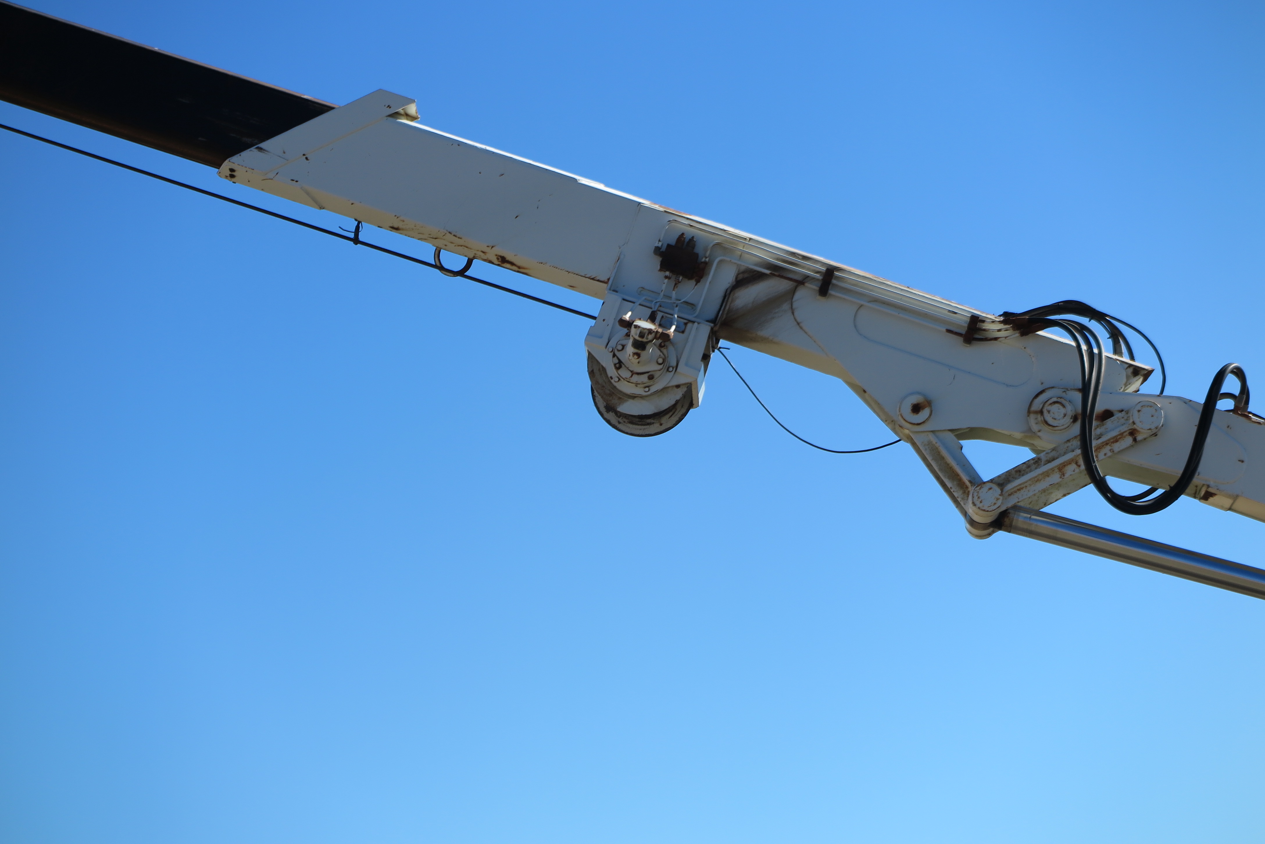
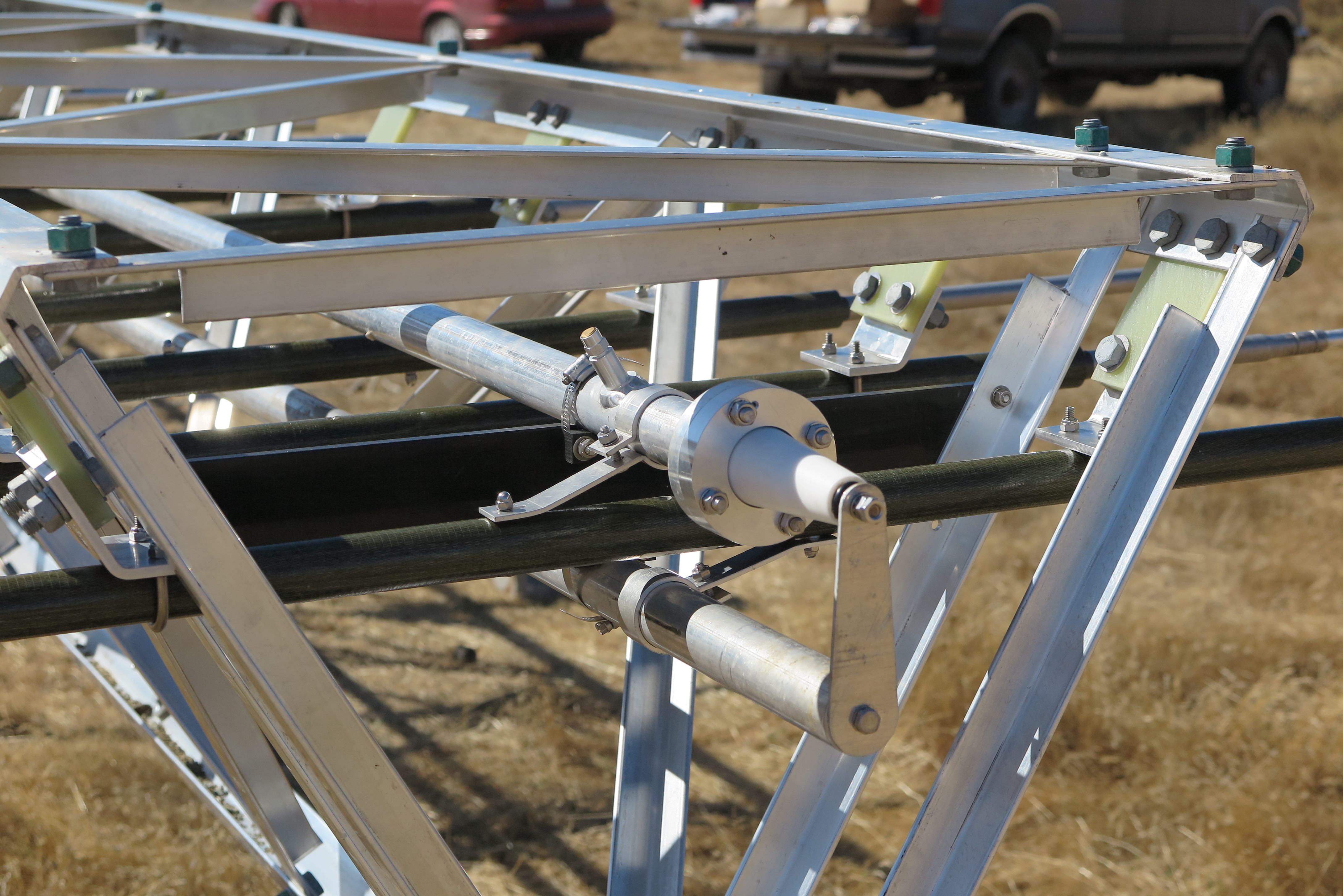
Crane with Boom Mounted Winch
My crane mounted winch will do the heavy lifting when it's time to erect the antenna. Here, I have strung the wire rope from the winch up through the pulley at the top of the tower, and then down to the mast. After the antenna boom has been bolted to the top of the mast, this winch can draw the mast upright. (hopefully)
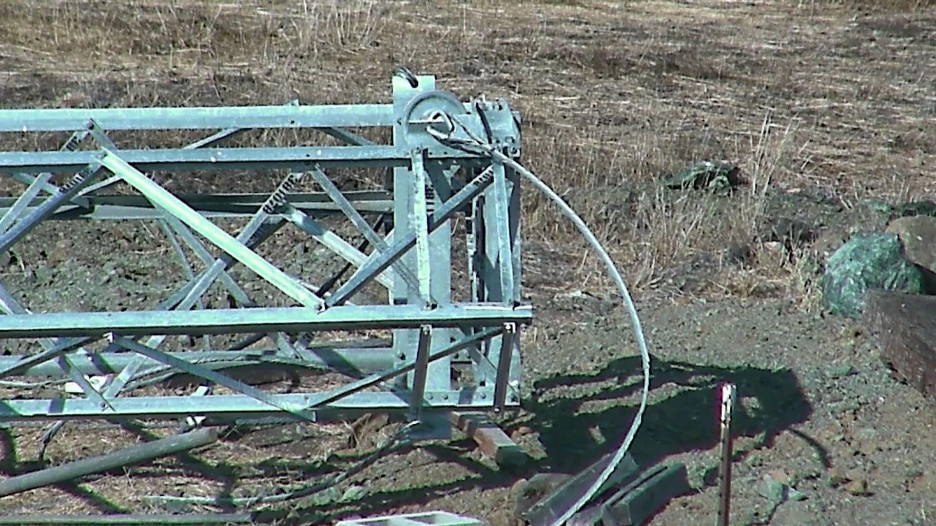
Erecting Winch
The winch has a rated 8000 pound pulling capacity on the first layer of the drum. I expect the antenna and mast to need 6000 pounds to raise it.
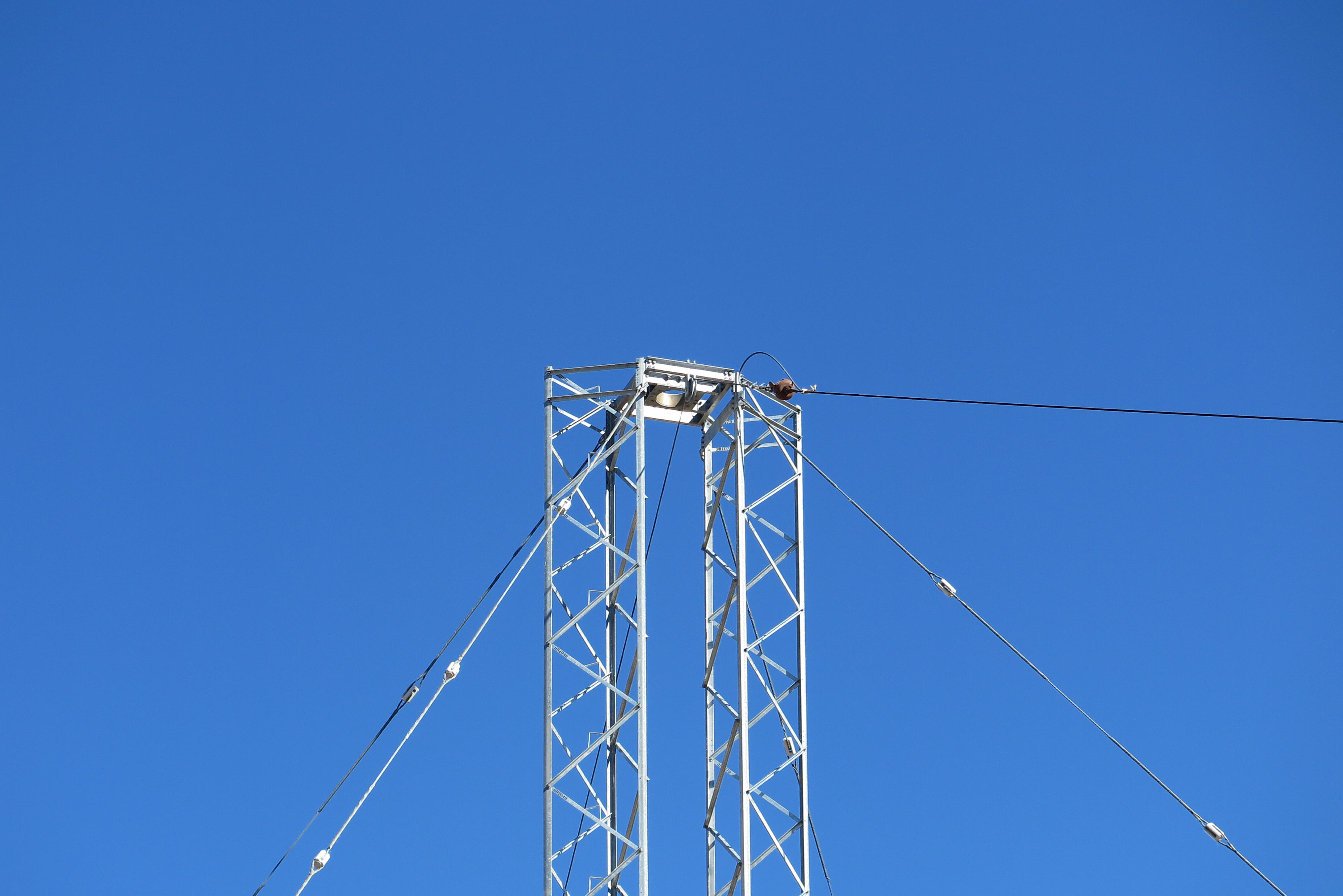
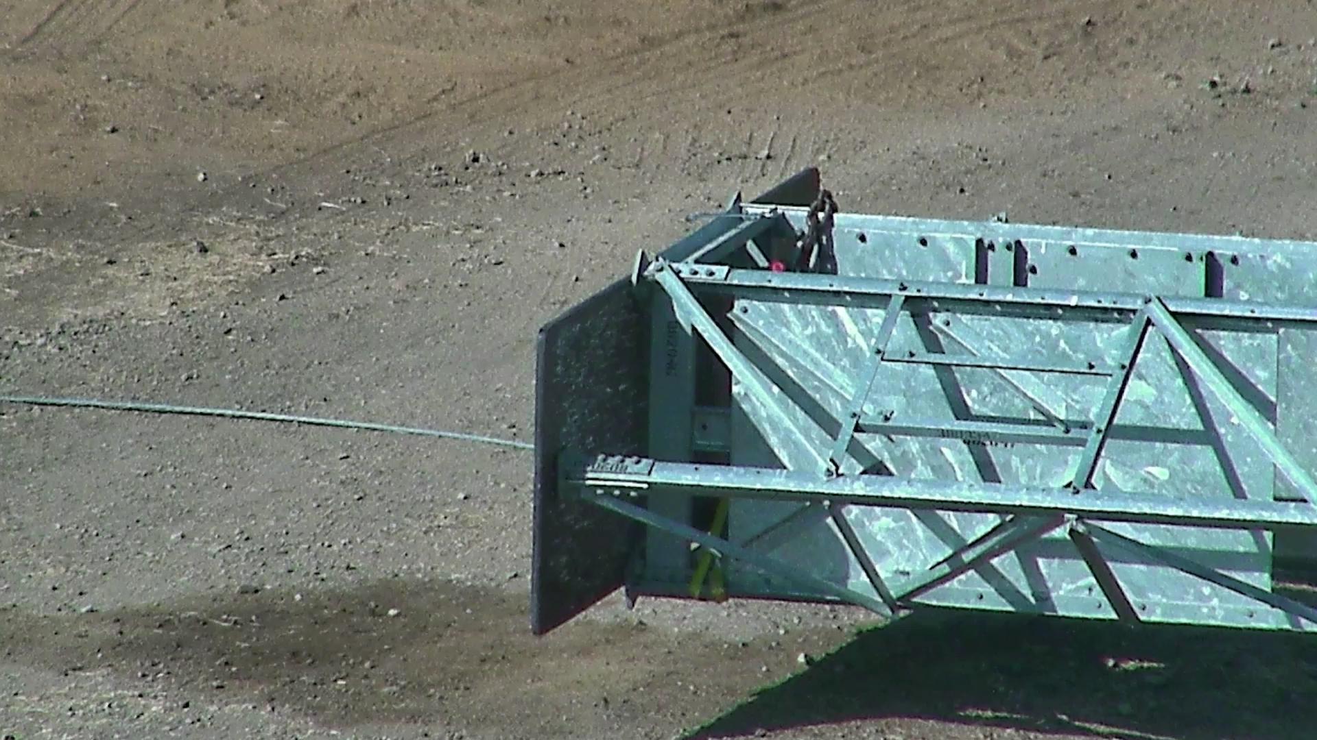
Tower Top with Erecting Pulley
Here is a view of the pulley at the top of the twin towers where the wire rope goes over the top and down to the mast attachment. The winch's headache ball is the round object at the wire rope junction point.
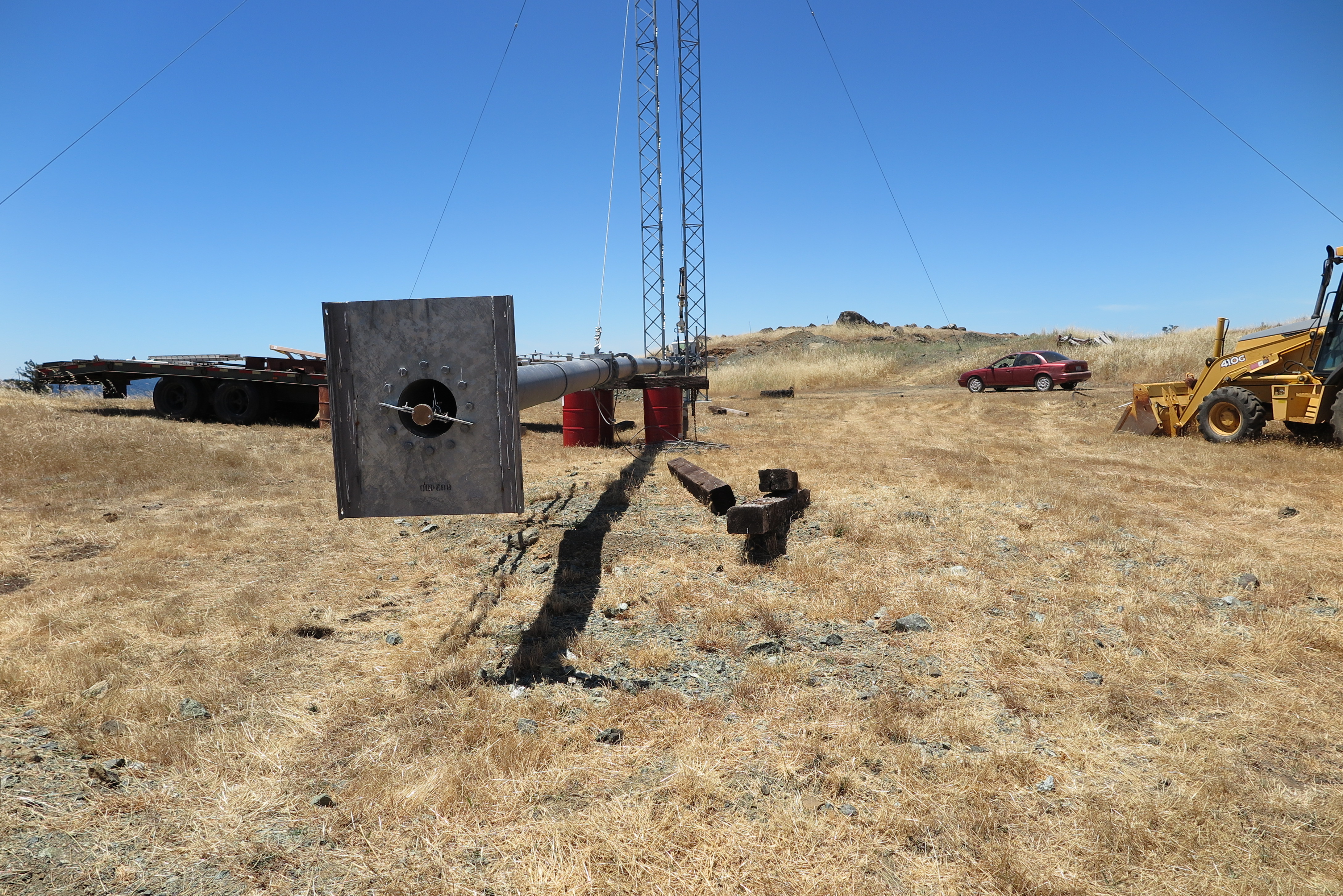
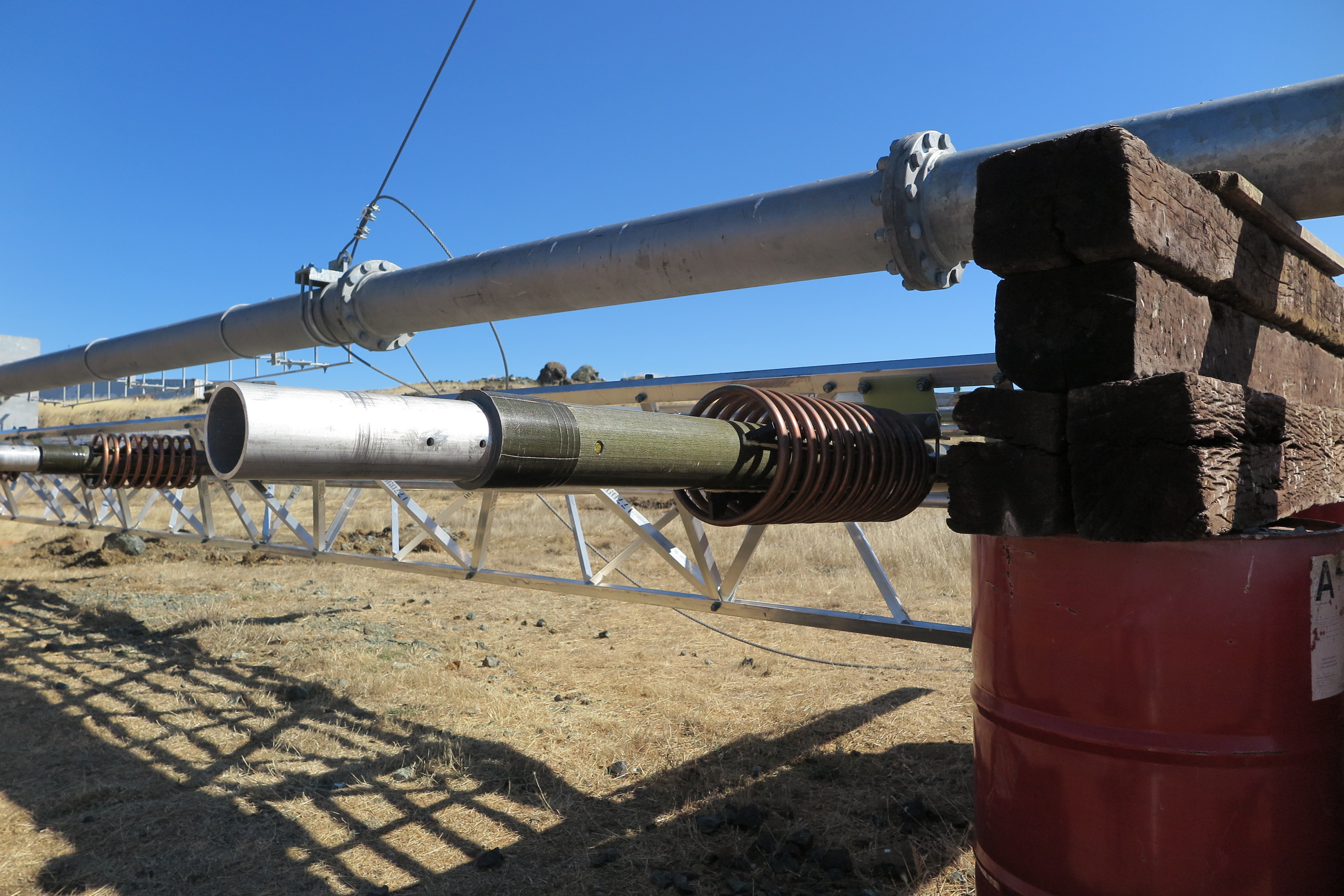
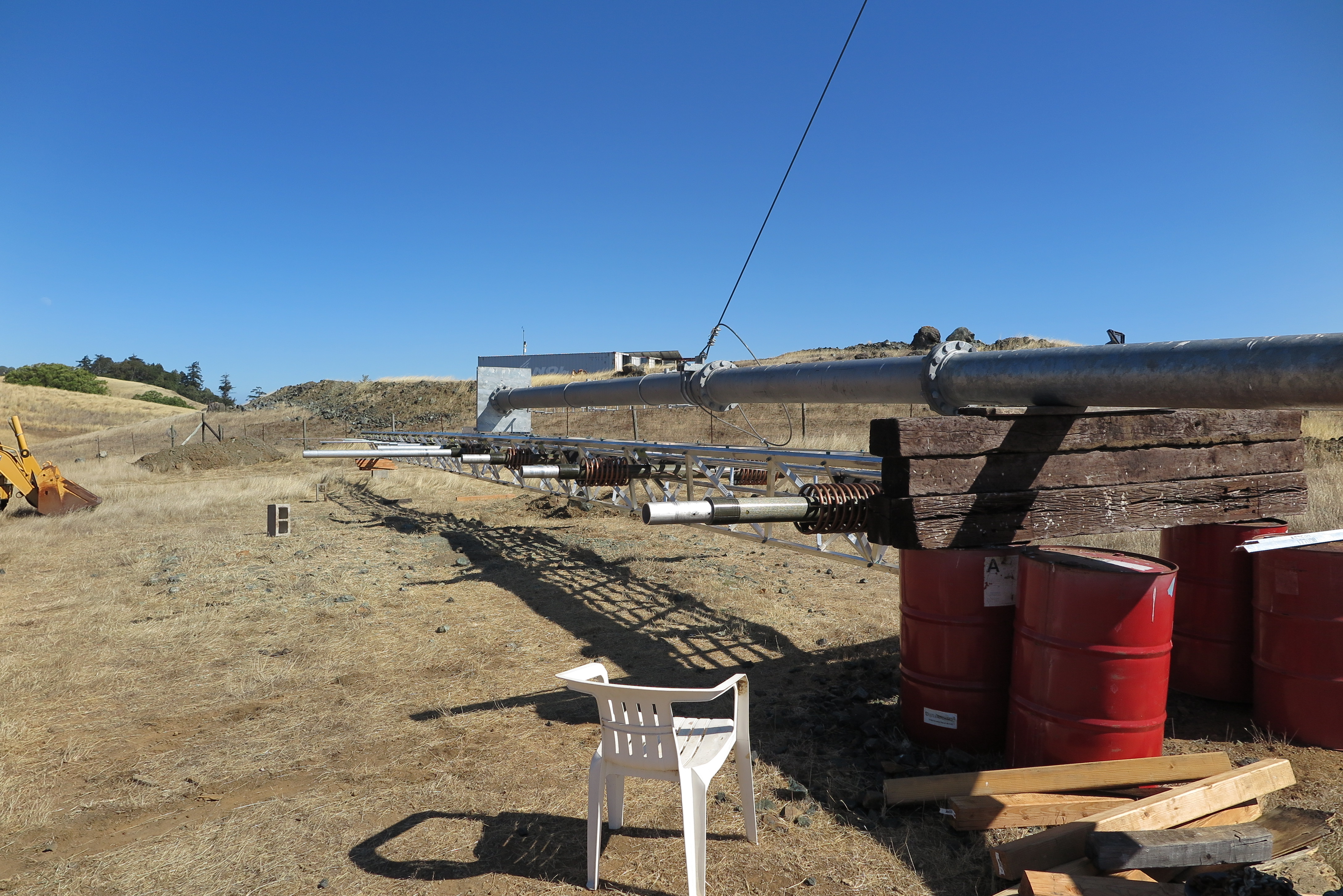
Mast Completed
This is a view of the mast from the antenna's mounting position. The parts in the middle of the mast are the feed line and it's mounting hardware. The EIA 1 5/8" feedline is an aluminum tube with a copper center conductor made to handle 50,000 Watts peak. As a licensed ham, I doubt this feedline will see more than 1500 Watts.
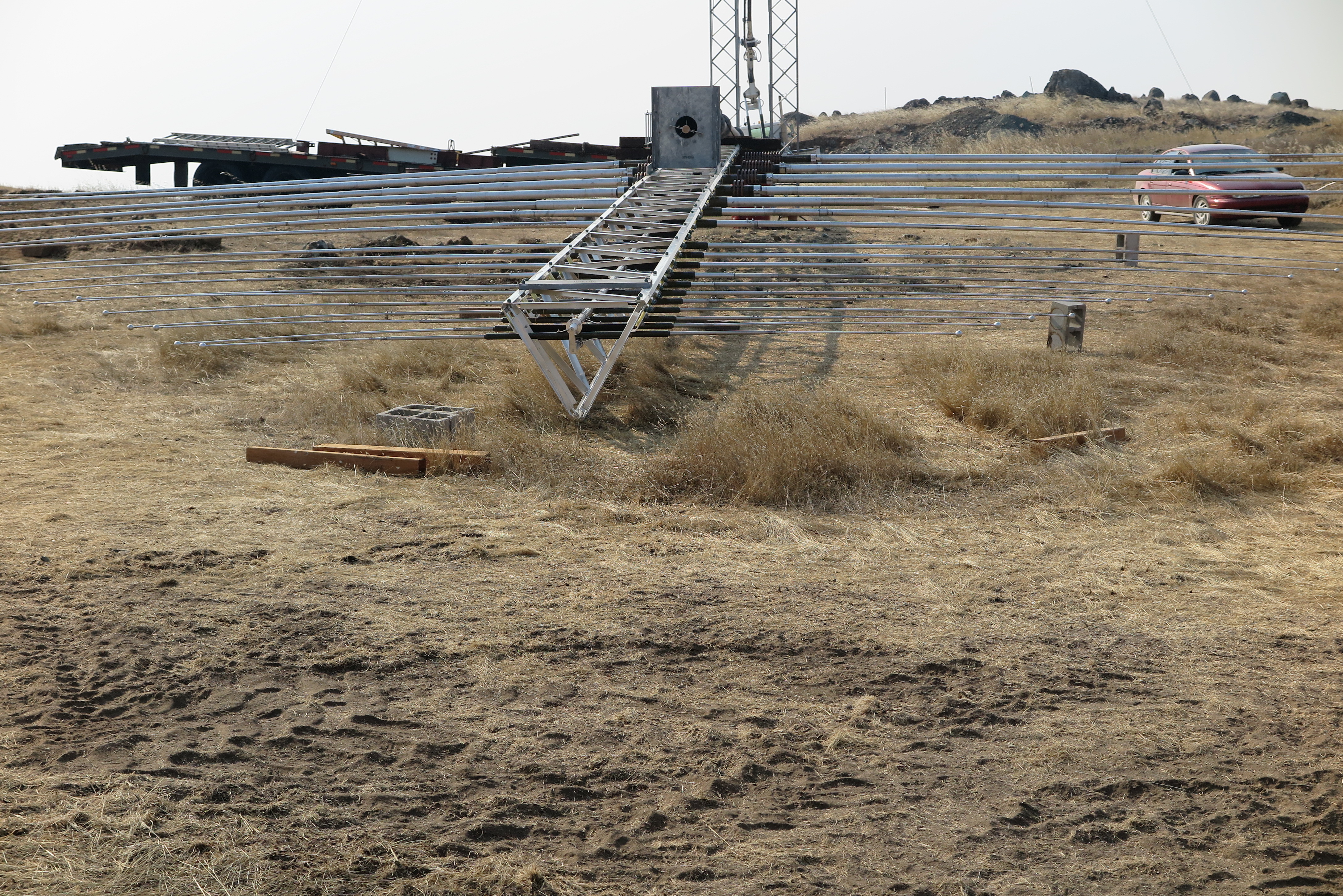
Trial Mast Erection
Well I guess the winch is able to lift just the mast, although it creaked a bit in doing so. With the antenna on the end of the mast, there will be thousands more pounds to lift. There is a bearing at the tower-top that holds the mast secure. At the real antenna erection time, half of the bearing is removed to allow the mast to swing into vertical position. In this test, I just wanted to see if the winch could lift the mast alone, which by-the-way is several thousand pounds itself. (schedule 60 steel tube)

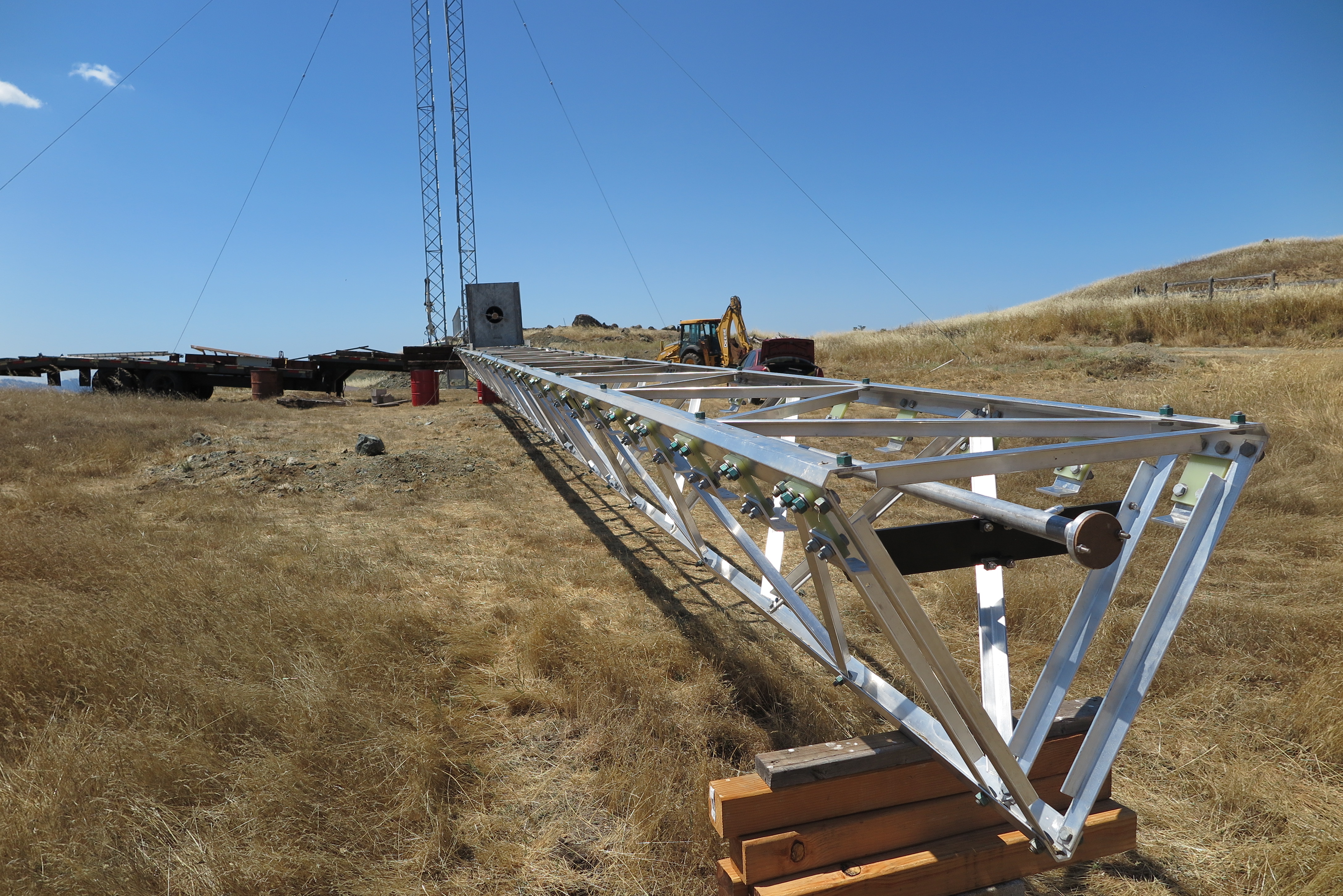
Naked Antenna Boom
I have completed the antenna boom, all aluminum to keep the weight to 3000 pounds or so. At this point, I have yet to torque the bolts. I ran out of patients running back and forth, trying to sight along the axis, and then propping-up the low points. The boom isn't perfectly straight, but close enough I hope.
Two Elements in Boom
I placed the front two elements, number's 1 and 2, just to see how they would look. This is their position on the boom, but I have not attached the mounting hardware at this juncture.
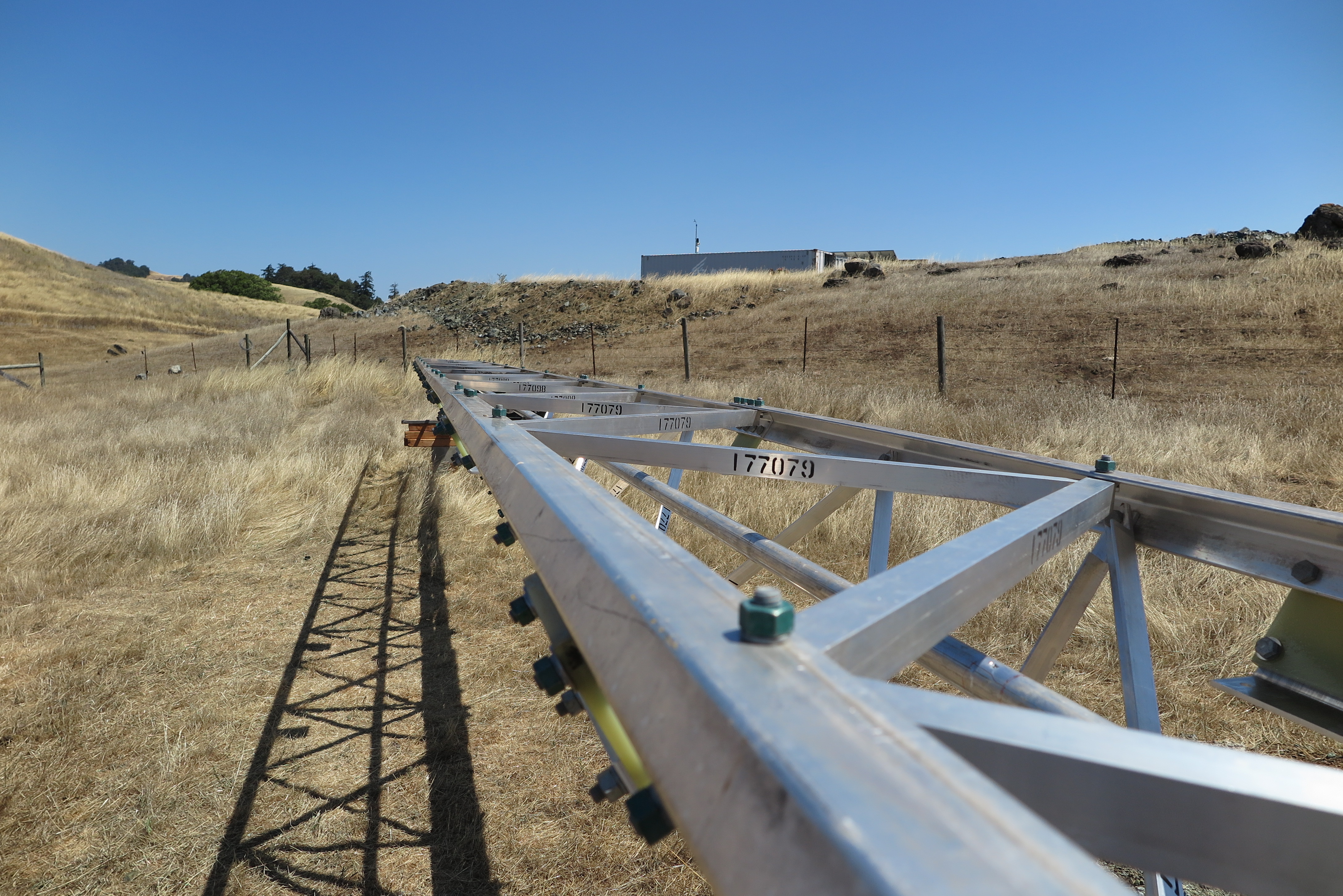
Boom Viewed from Front
After another week's worth of work, I moved the completed boom which is 72 feet in length from the flattest area where I assembled it, to the antenna site. This was not an easy feat! The picture shows the antenna shot from the front (smallest elements), looking toward the back (longest elements). Once the boom was bolted to the mast, I then installed the element support brackets, and the main 1 5/8" EIA transmission line.

Boom from Back View
Here is a view from the back end of the antenna, looking toward the front. As the mast is raised with the truck winch, the antenna will pivot on the mast mounting plate until at some point, the antenna will be perpendicular to the mast, and I can climb up the back end of the antenna boom to place the remaining two bolts in the mast plate. I will also need to join the transmission line which comes up through the mast center to the mating transmission line fitting from the antenna. Following that, I can proceed with raising the mast to its full vertical height.
Perforation in Transmission Line
If you look at the transmission line just to the right of the cross brace, you can see a perforation which was caused by a screw which was driven into a wooden cross plate in the transportation crate at the factory. The cross board was intended to clamp the transmission line sections in the crate during transport. Because of the careless assembly, I now have a small hole to repair. The transmission line is 1 5/8" EIA rigid aluminum tube with a brass center conductor. To repair the hole, my original attempt was to remove the center conductor, and then using an aluminum brazing kit, seal the hole. When I attempted to remove the center brass conductor, the Teflon support spacers began to catch on the perforation which apparently protrudes somewhat on the inside of the tube. I needed the center conductor out of the tube, because I have to heat the tube in order to braze the hole closed. I didn't want to melt the spacers in the vicinity of the repair site. Anyway, since I couldn't remove the center conductor, I pushed it back in, and am now going to effect a repair with epoxy. The transmission line is pressurized with nitrogen, mainly to keep the rotary joint dry, and I can't have a pinpoint hole anywhere in the transmission line.
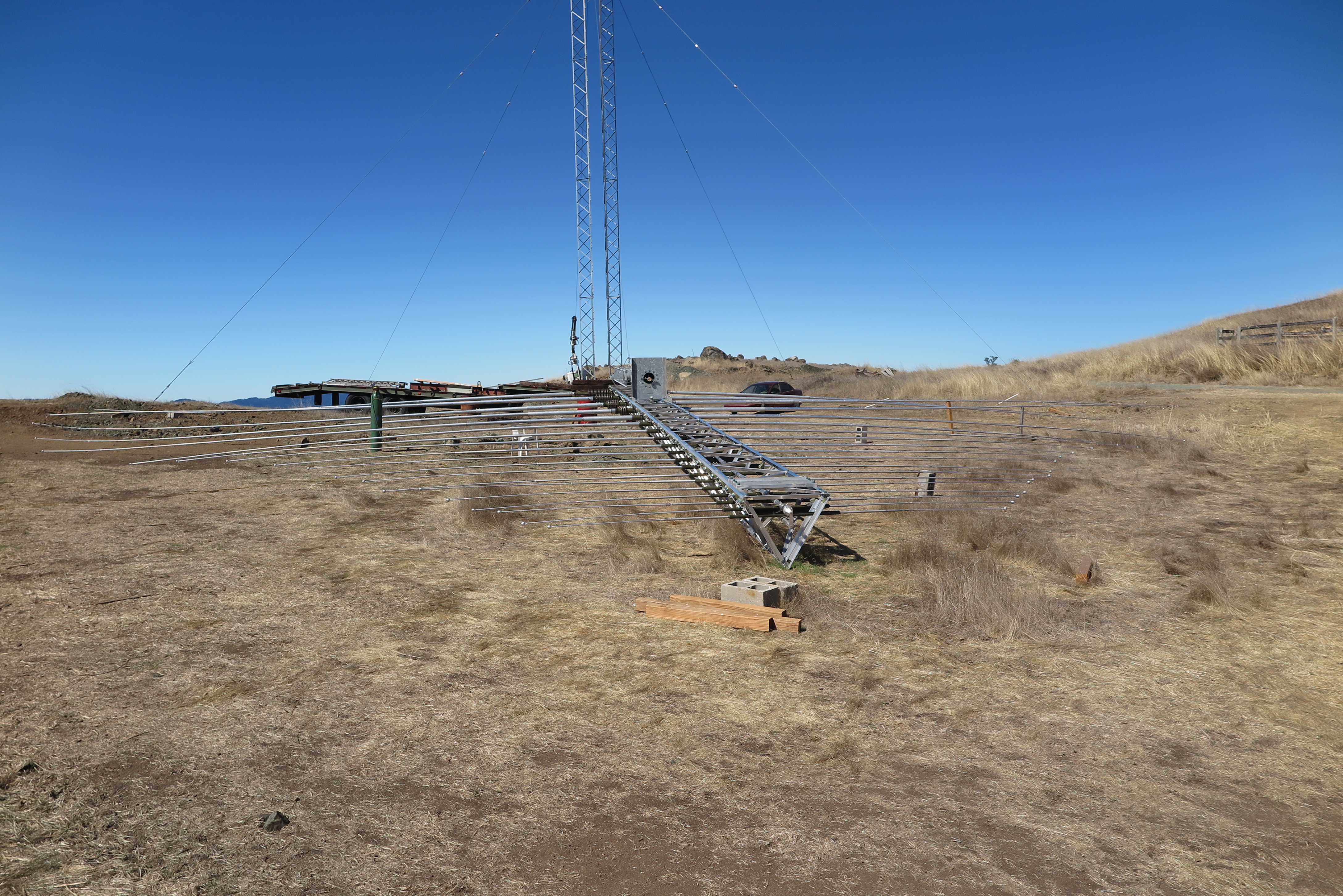
Antenna and Tower no Elements
Here is a final view before I begin mounting the 19 elements into the boom of the antenna, and the twin towers in the background. Just visible is the wire rope which attaches to the mast, goes up through a pulley in the towers, and down to the winch truck way off behind.

Antenna with Bare Elements
Finally with the elements installed the LPA is starting to look like an antenna! The last (rear of antenna) four elements visible here are foreshortened, and inductively loaded. These are elements 19, 18, 17, and 16 numbering from the rear toward the front.
As can be seen along the mast, birds are going to be a BIG problem...
Element 19
The last element toward the rear of the antenna is element 19 and is the longest at 104 feet. Installed here, is just the insulator part with loading coils, and the pipe stubs that will hold telescoping extensions to be installed later.

Elements 18 and 19
Here is a view of the left side of the antenna, with elements 18 and 19 visible. Again, only the insulator, loading coils, and tube stubs have been installed. This is the left side because the antenna is upside-down here, and will swing down when I raise the mast.
Antenna from Rear
Looking along the antenna back-to-front with just the element support insulators, and tube stubs installed.
Mid-section to Front
This view is from mid-section looking toward the front of the antenna. Only the first two elements way to the front are complete with the metal balls attached. These are elements one and two, and are the only elements out of the 19 total that were factory assembled.
Feed Terminator
This is the front of the antenna where the transmission line terminates. The transmission 1 5/8" EIA hardline forms a BALUN along the length of the boom. At the feed point it is a 50 Ohm line, but as the sections join together, the center conductor keeps getting smaller, such that the line impedance is increasing until it gets to this point where it breaks out into a termination. The termination (center conductor) then traverses back the length of the boom above the 1 5/8s EIA, forming the other half of the feed line pair. Each element attaches to both the outer conductor of the coax EIA, and the other conductor with alternating phase on every element. This is the standard connection configuration for an LPDA antenna. The small object protruding at an angle near the end of the feedline is a 21 PSI pressure relief valve. The feedline will be pressurized with dry nitrogen, and at the line pressurization time, with a slight overpressure at the nitrogen source, the air in the line will be purged. You can clearly see the dipole attachments for this element number one, fully installed here. Only 18 more to go...
Right-rear View
After another 10 days' labor, I have the antenna mostly constructed. I knew from the get-go that I was going to have to shave-off the up-slope hill in order for elements 16, 17, 18, and 19, to stretch out in that direction. Element 19 for example is 104.16 feet long. This picture shows the nearly completed antenna from behind with the hill reduced. The elements still touch the ground, but without any dirt removal, they never would have had a chance.

Left Front View
It took half a day to remove the up-slope hillside which was blocking the back elements. One huge boulder amazed me in that my little Deere 410G was able to lift it out. It is really boring to the extreme, making pass-after-pass with the loader to remove the dirt.
Full Front View
Here is a full front view of the nearly completed antenna. The antenna has been constructed upside down, so when the mast is raised, it will pivot on the mast support plate into position. Note that it is actually looking like an antenna now. Sort-of a TV antenna on steroids...
See the gap at element 12? The center insulator was fabricated with different wall thickness tube. The fiberglass insulator has two aluminum tubes with the fiberglass molded around them. Unfortunately, the fabricator must have picked up one correct sized tube, and another with the same outside diameter, but a thinner wall thickness. I can see how that could happen, but now I am waiting for resolution to the problem from USAP. There are only a few days up here when the wind is below 15 MPH for hours at a stretch, and those days are when a high pressure ridge parks over California, and the temperatures are high. I need less than 15 MPH to raise it.
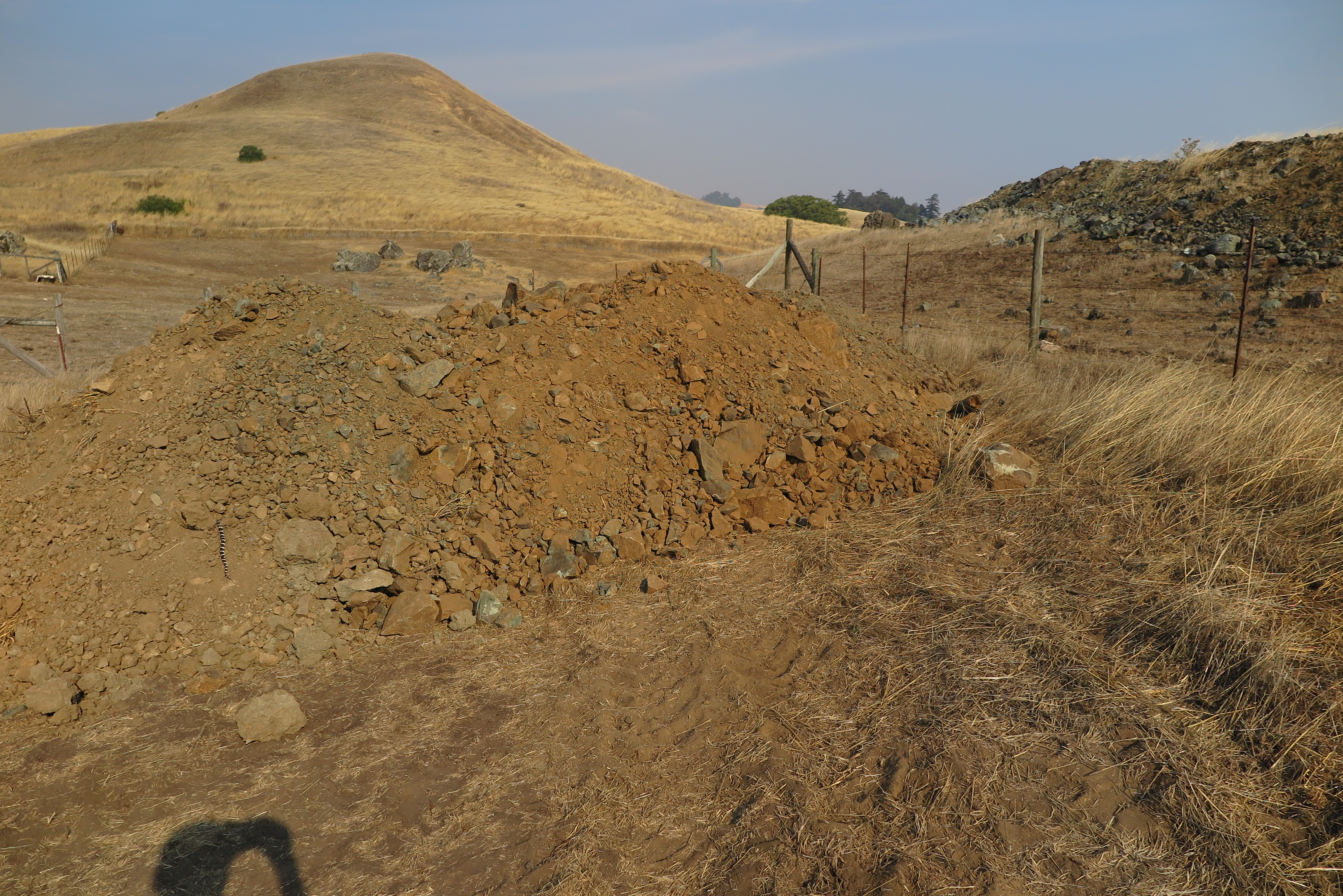
Dirt Pile from Hill
Here is the pile of dirt and rock removed from the up-sloping hill. Note the Common King snake at the lower left, checking out a possible new home. I have lots of different varieties of snake up here including rattlers, which help control the destructive rodents.

Back Elements
Here are the back elements. Elements 16, 17, 18, and 19 are inductively loaded because of their foreshortening. In addition, elements 18, and 19 have capacitive hats on the ends to electrically extend the element's length. The way USAP fabricated the center insulators, these T-bar end capacitive hats are vertical. The construction book, and an e-mail to USAP confirmed that they are supposed to be horizontal. I personally don't think it would make much difference, but I'll have to drill new holes in the telescoping tubing at 90 degrees to get their orientation correct.
The rear elements have a lot of droop. A truss above the boom with stays out to the longer elements would have been nice...

Element 19 T-Bar
Elements 18 and 19 not only have inductive loading to make them look longer electrically, but they also have capacitive hats on the ends for the same purpose. Due to sloppy construction practice at the factory where these elements were made, the T-bars were at arbitrary angles. An e-mail confirmed that the design was for them to be horizontal, so I had to drill new mounting holes in the telescoping tube to properly align the T-bars.
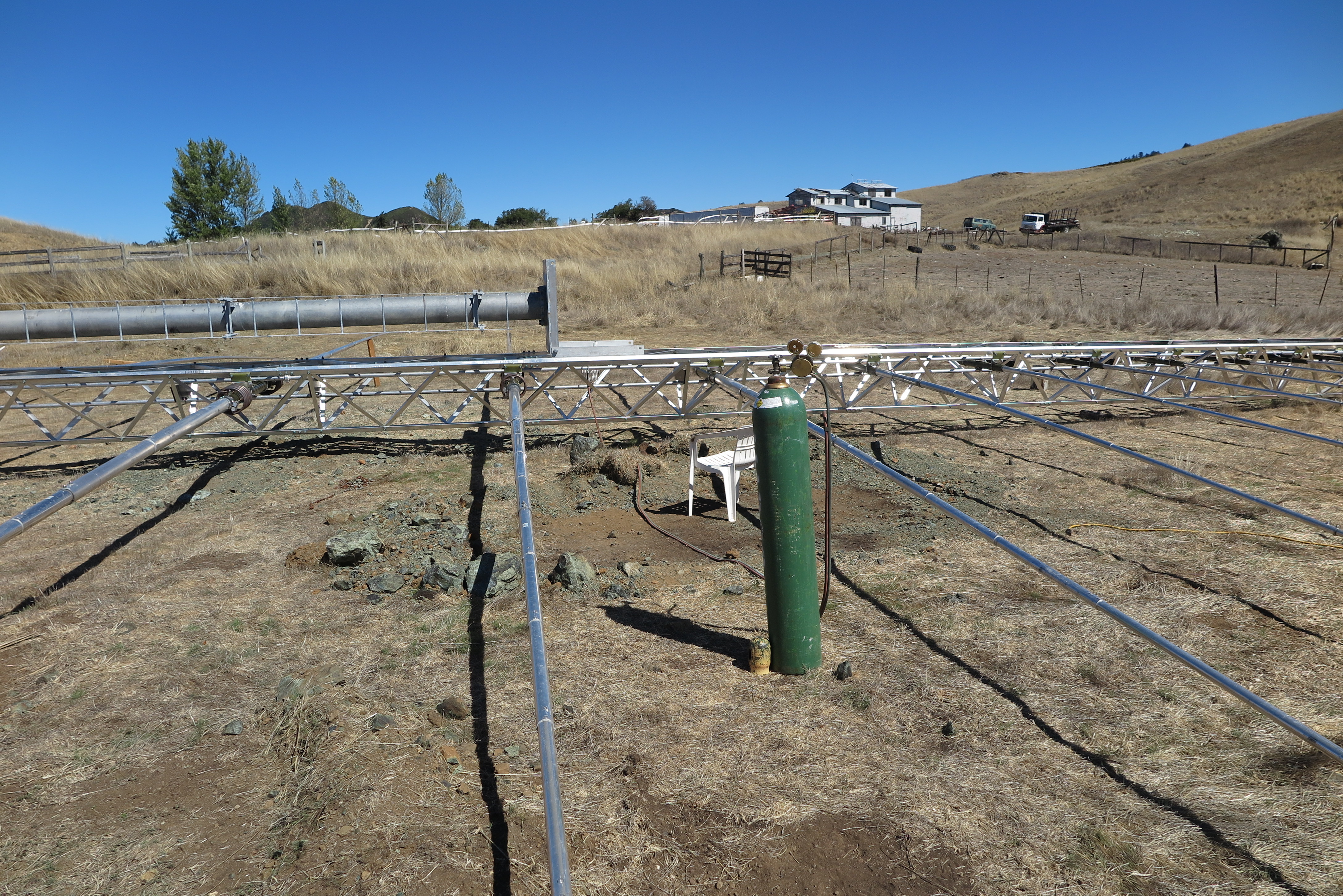
Pressure Test
I had a left over helium tank from the Mendocino County's ridiculous balloon test (they had me fly a balloon at 100 feet to see what the antenna would look like) for my variance, but because the regulator was leaking, I used oxygen for the feedline pressure test. There is probably no worse gas to use, well no, fluorine would have been worse, but oxygen was on hand and the plumbing matched for the pressure test.
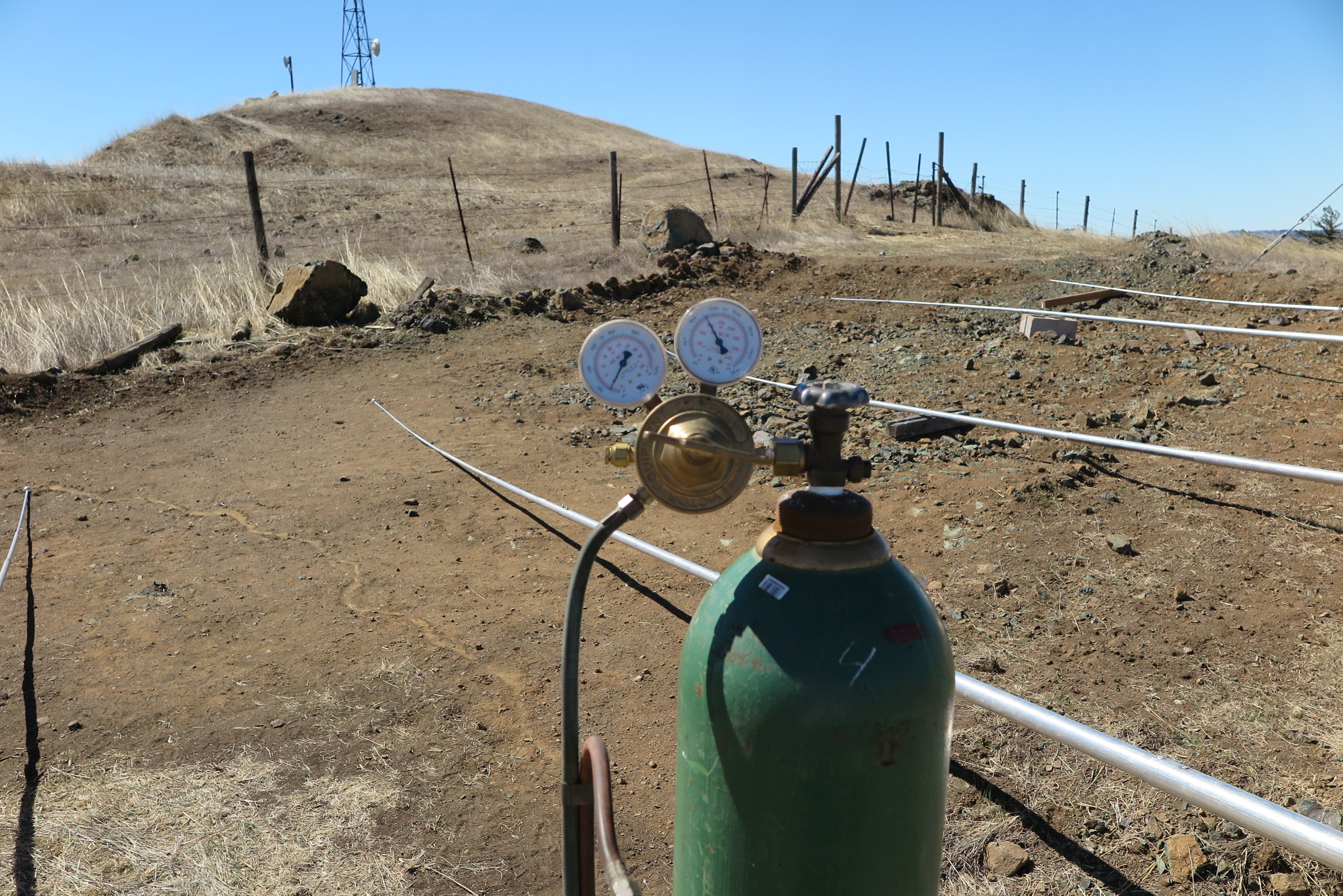
Oxygen Meters
I didn't have to do any trouble shooting on the transmission line interconnections, as the pressure held at 20 PSI for a couple days. The slow leak-down (several days) was due to the swivel connections in the oxygen hose. I've noticed this before when using the oxy-acetylene cutting torch.
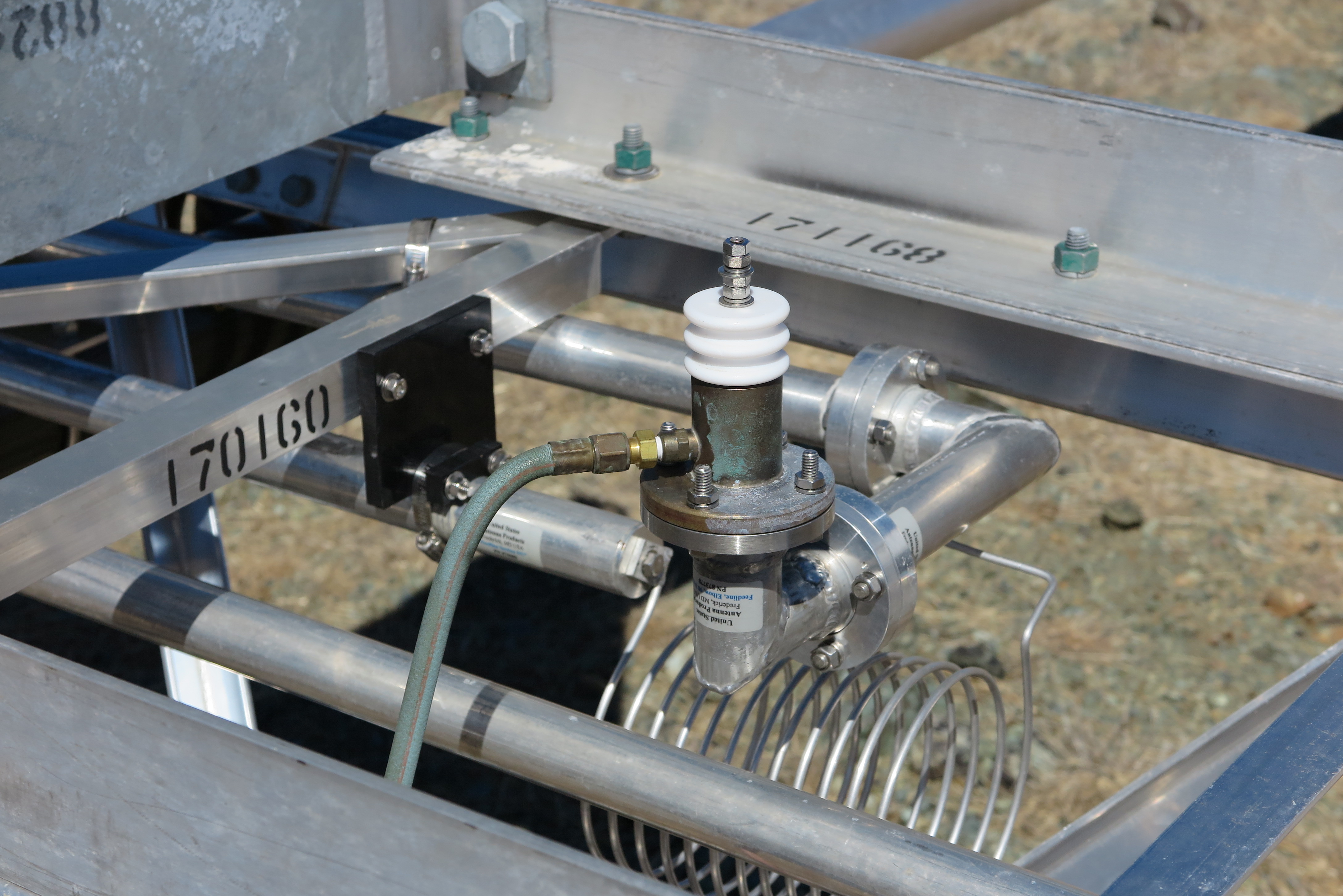
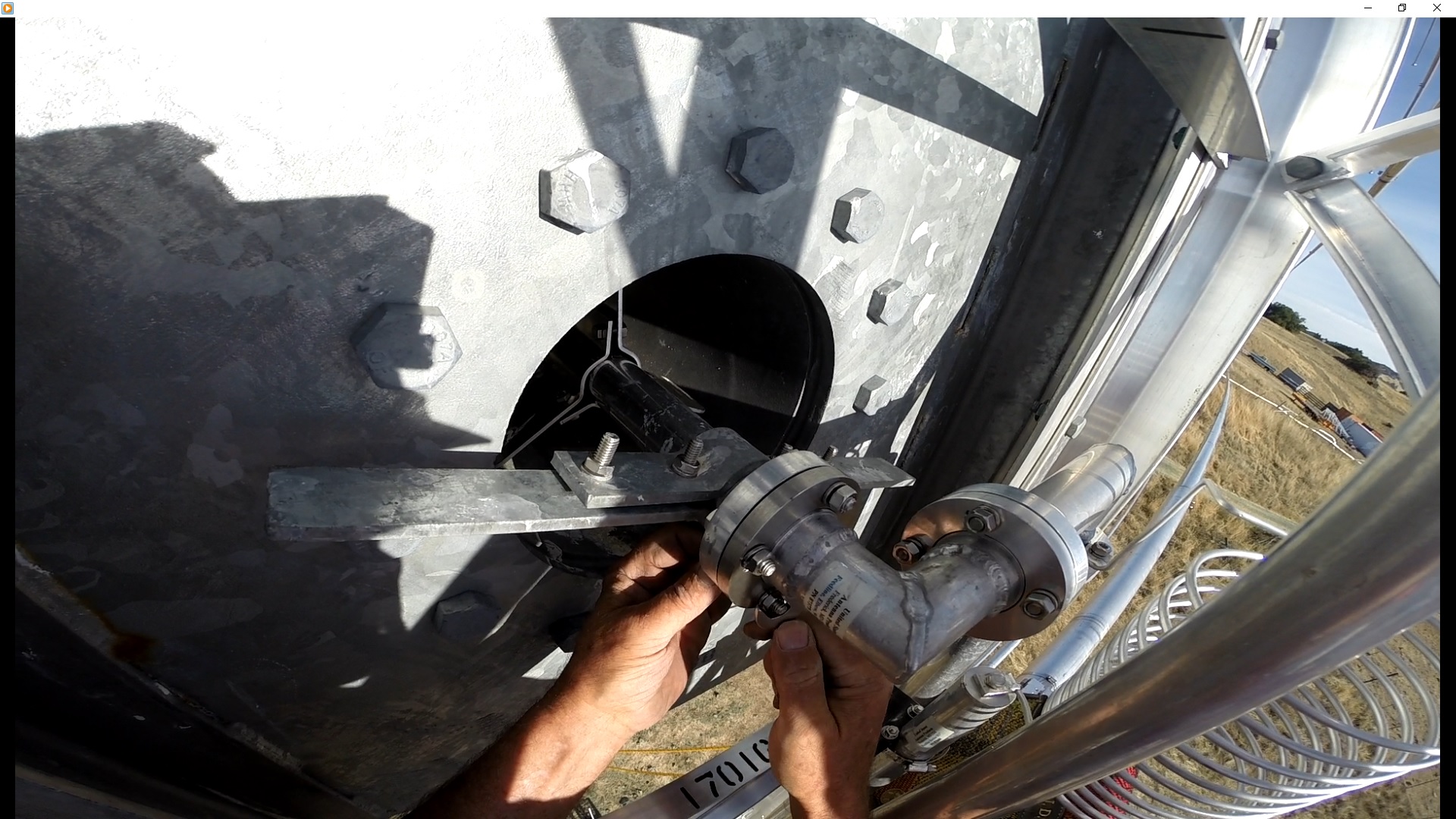
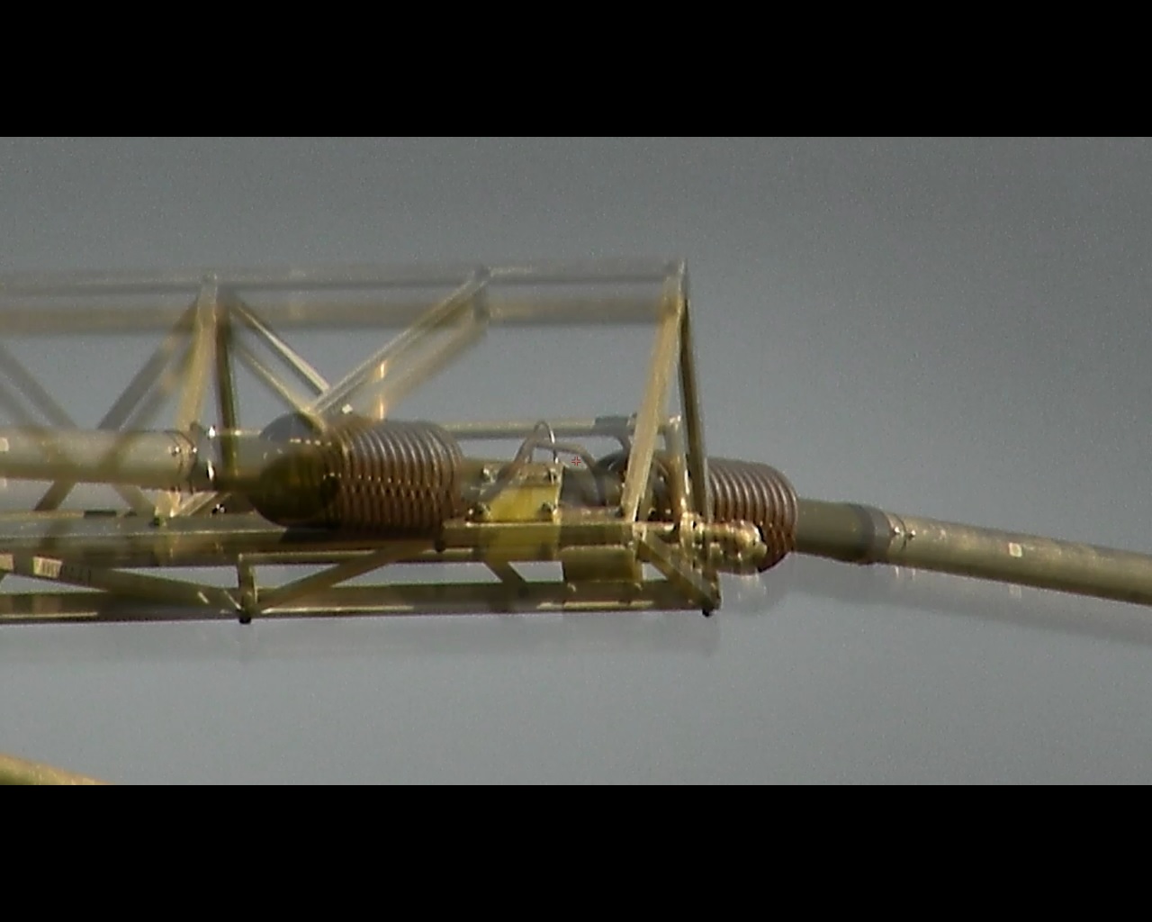
Feed Plumbing Tree
This image is looking at the mast plate to antenna boom connection. The termination with the oxygen hose connection is simply a 1 5/8" EIA termination I had around from another antenna. The final connection to the antenna's feed will be made when the boom swivels up into the mast plate. The main feed line runs down through the middle of the mast tube to a rotary joint in the rotor at the ground level.
The aluminum inductor is the termination off the feed BALUN pipe that it is connected to. I'm assuming the designer wanted a DC short at the end of the feed's center conductor, but with negligible loading at RF. The coil bobs around in the wind, so I may stabilize it with some supports after the antenna is upright.
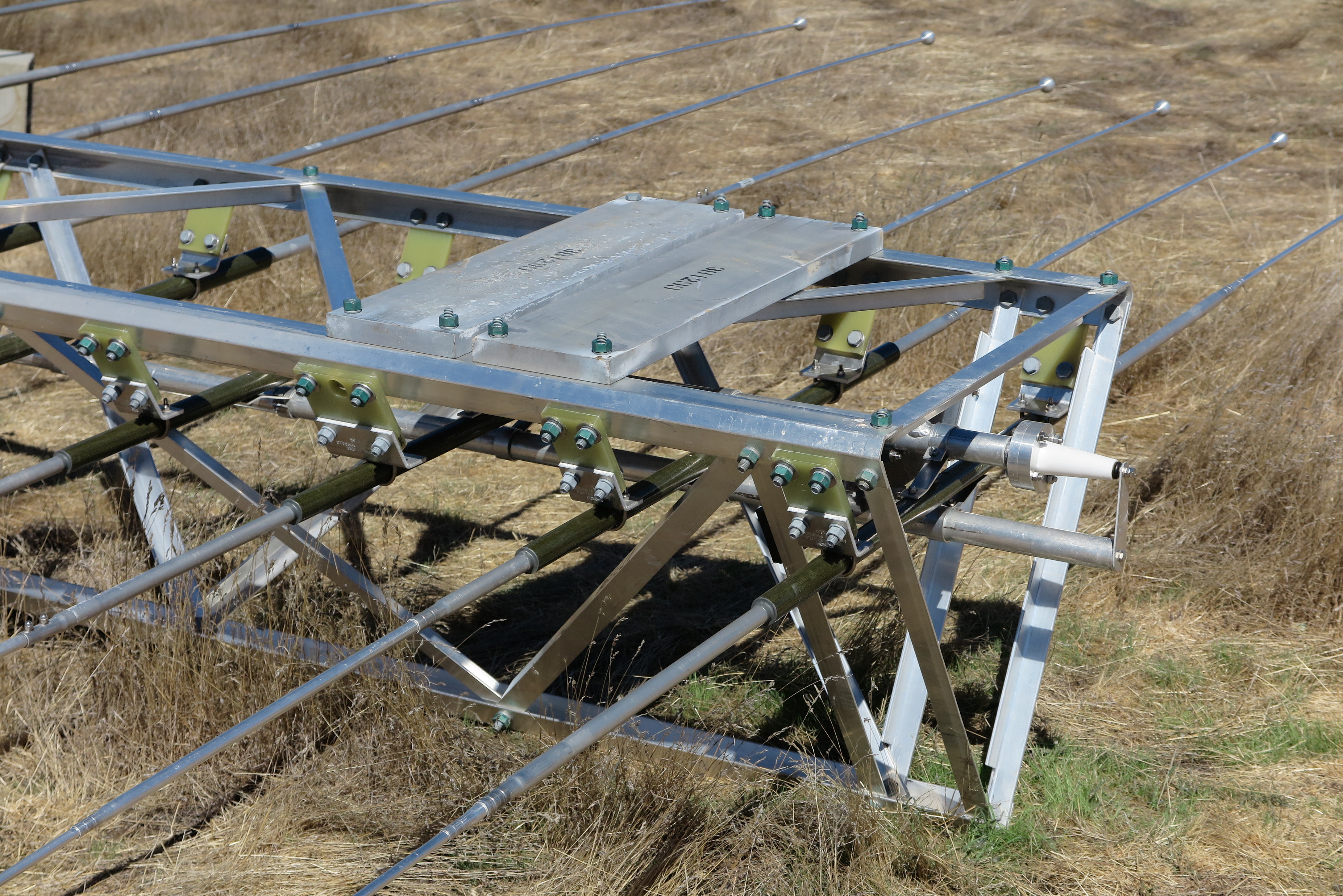
Counter Weights
There are 2 counter weights on the nose end of the antenna. They are each about 75 pounds, and make the nose a bit heavy, balance-wise. This assures that when the mast is raised to about 30 degrees, that the boom will swivel into place against the mast plate, so I can climb the boom and place the final 2 bolts into the mast plate/antenna boom interface. These bolts need 200 foot pounds of torque, which may be a bit tricky while hanging on the boom.
Finished Antenna
Here is a final view of the completely constructed antenna before erection day. I have gone over every bolt and nut in the entire antenna, some more than once, for a final torquing. At this juncture (Oct 3rd, 2015) I'm waiting for a calm day for the erection. At the moment there is a weather front heading our way, so it may be a few days to make it happen.
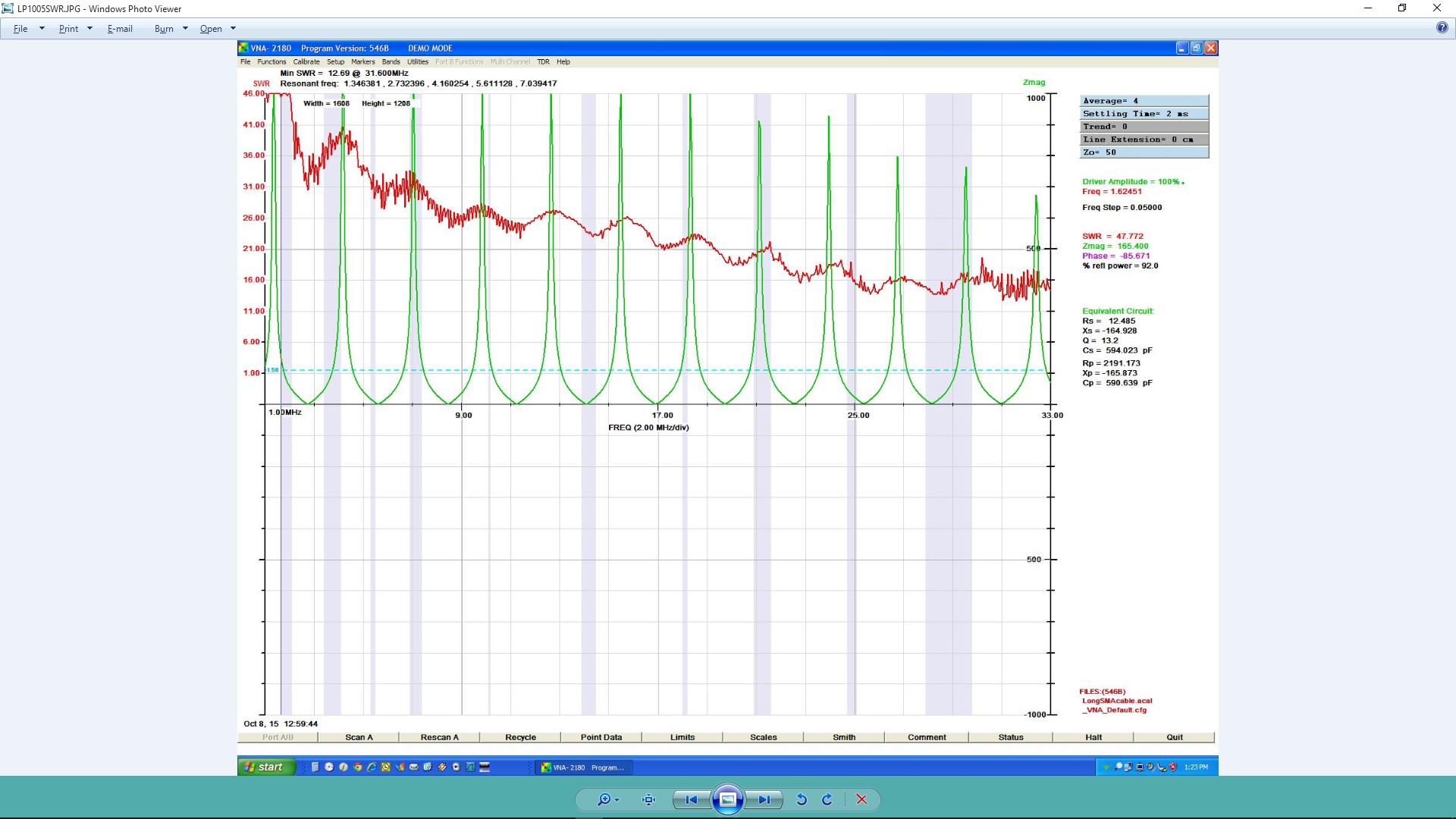
VSWR Plot
This VSWR plot was taken with the antenna completely constructed. It clearly is horrible, but after consulting with antenna experts from the reflector TowerTalk, I was convinced that because the antenna was resting on the ground, or very near to it, that the VSWR would be expected to be bad.
I should have trusted my own instincts, and suspicions that this VSWR was so bad that it couldn't possibly have been solely due to ground capacitance, but I didn't, and proceeded to erect the antenna anyway. This stupid mistake cost me > $14,000 almost all for naught.
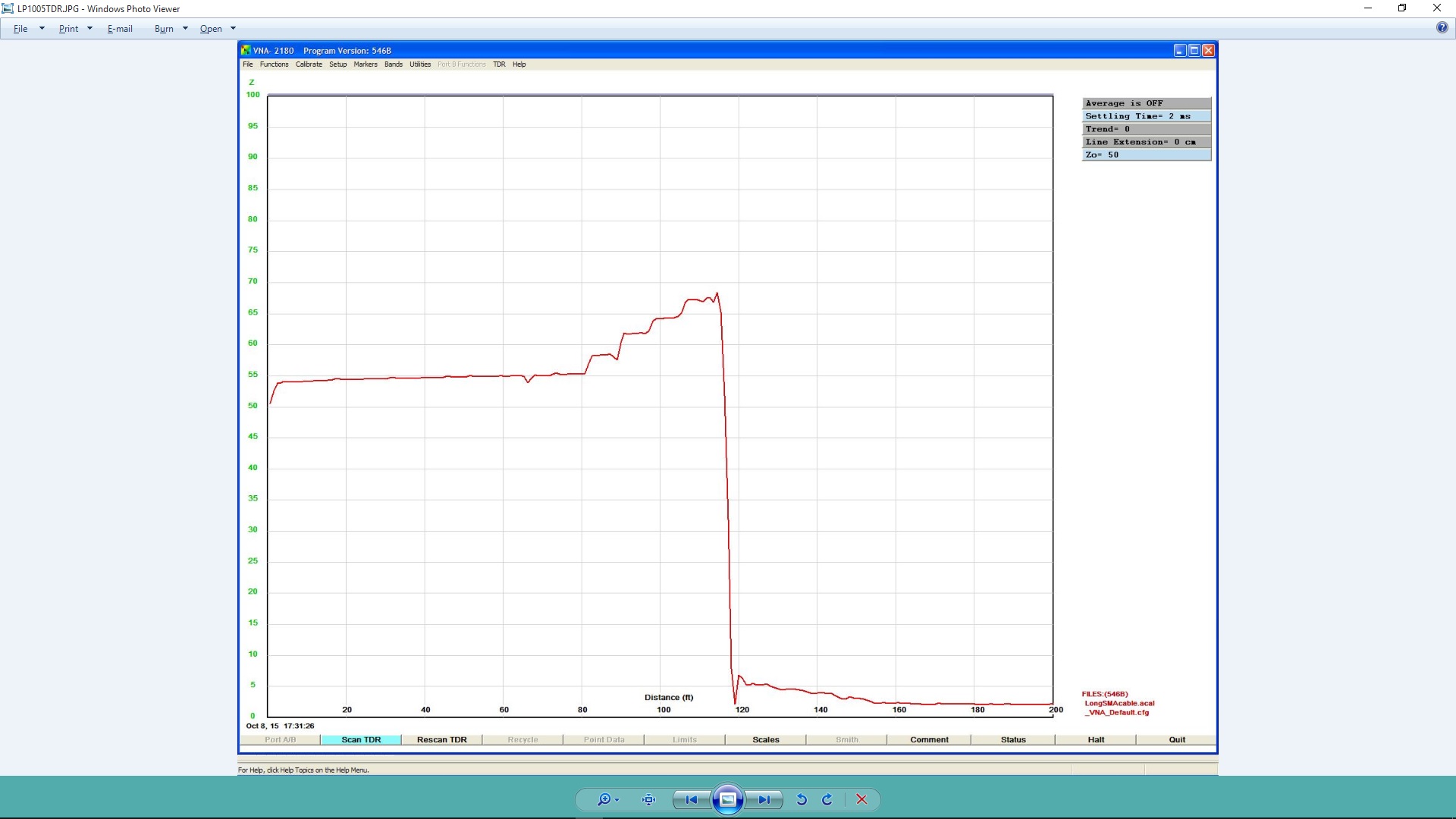
TDR Plot
The Time Domain Reflectometer plot shows Z0 vs. distance in feet. The first small dip is the rotary joint. The four steps are the tapered transmission line transformer with the impedance increasing toward 73 Ohms. The nasty fall to 5 Ohms I thought was the antenna itself, but it turned out to be the tapered transmission line, which had a near short.
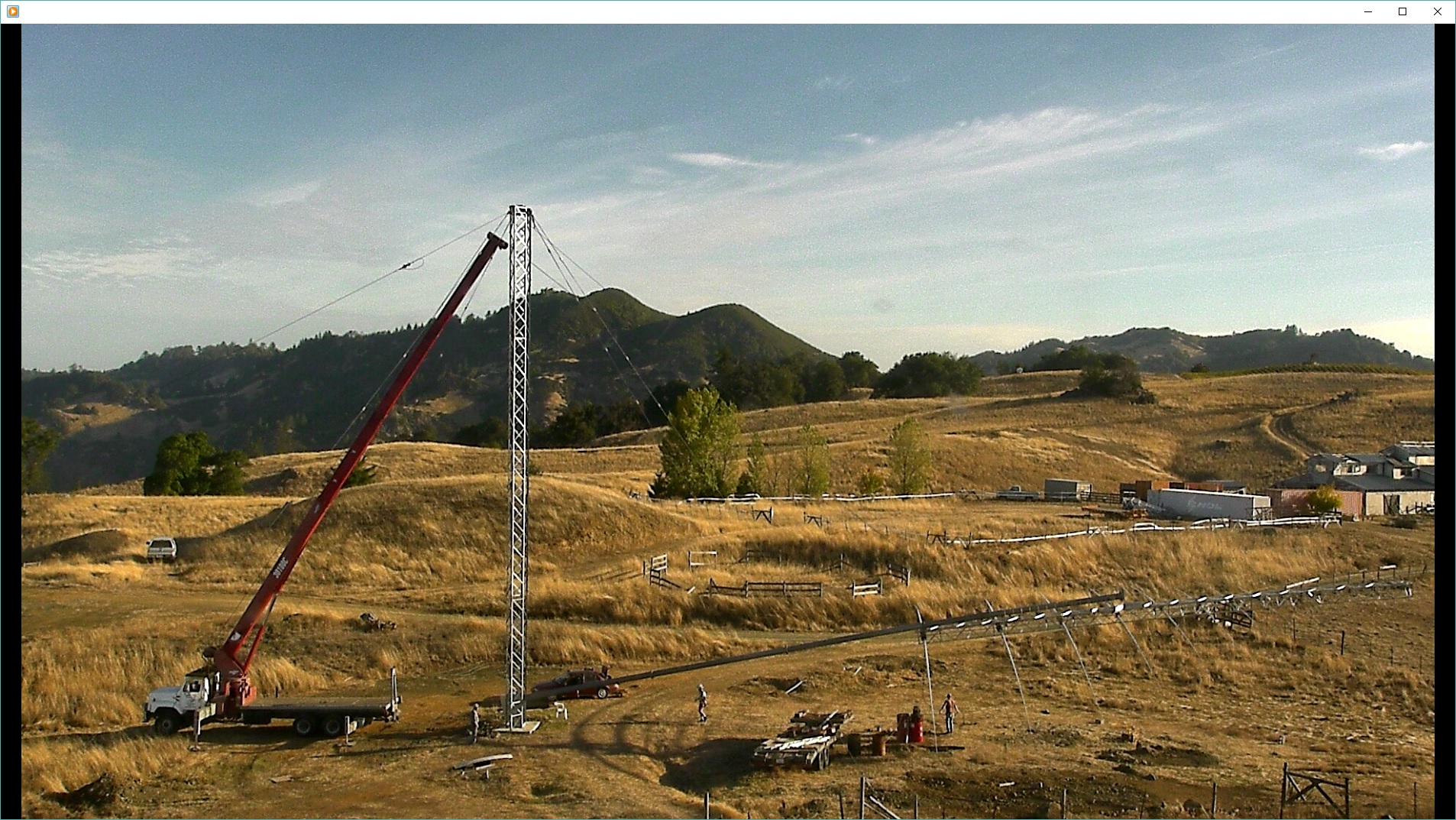
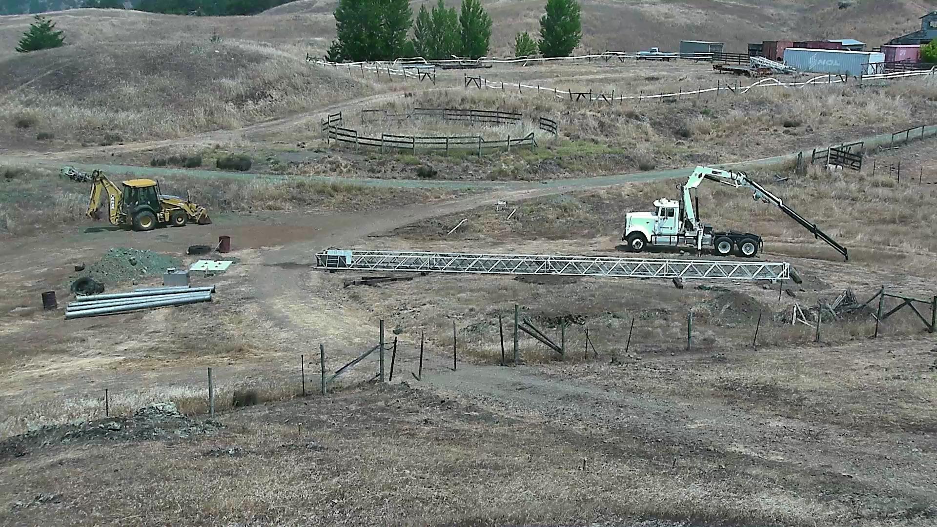
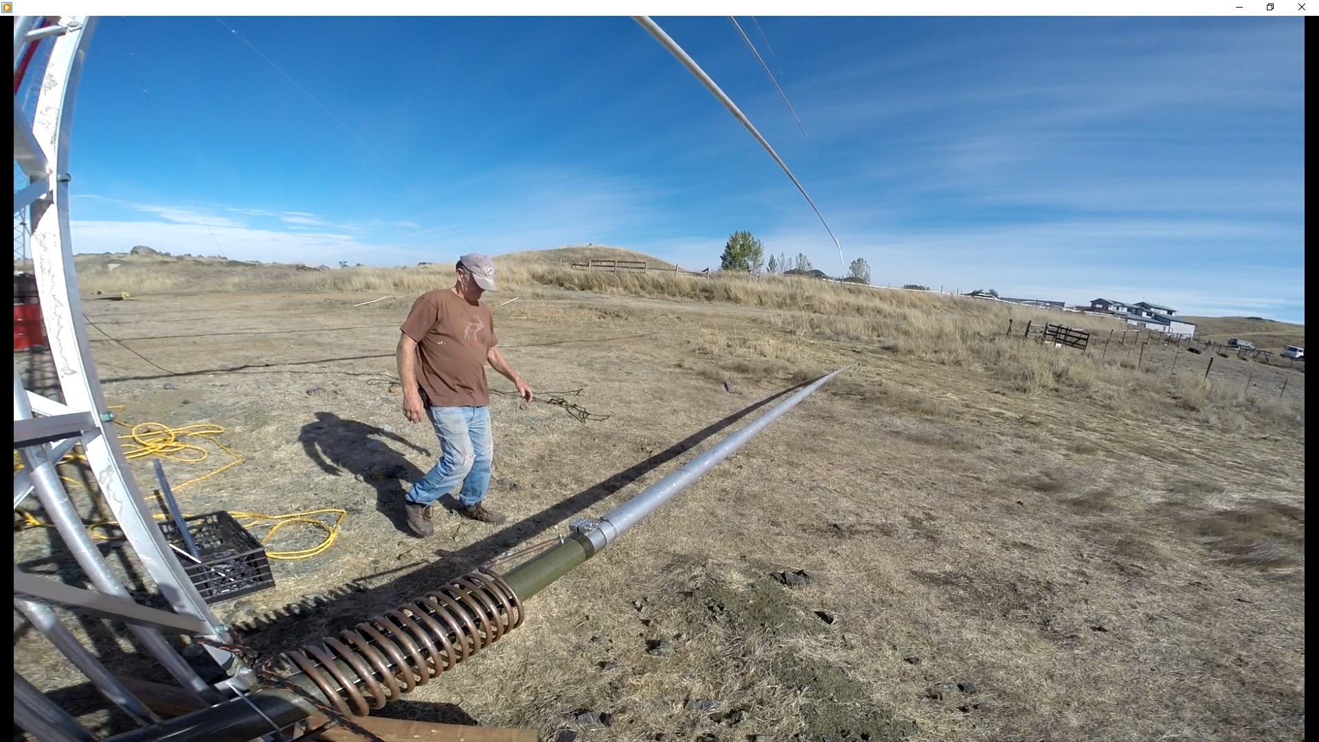
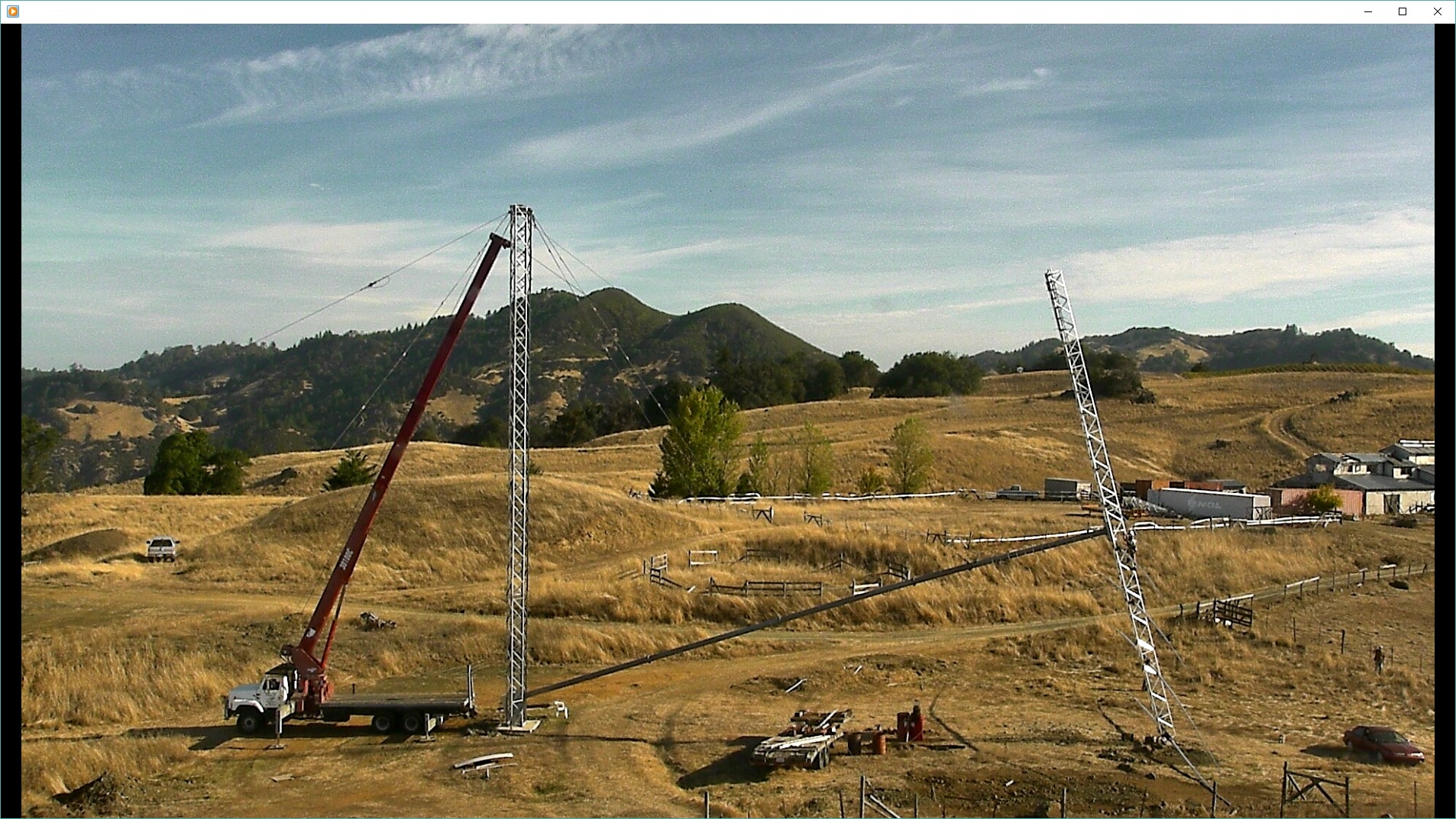
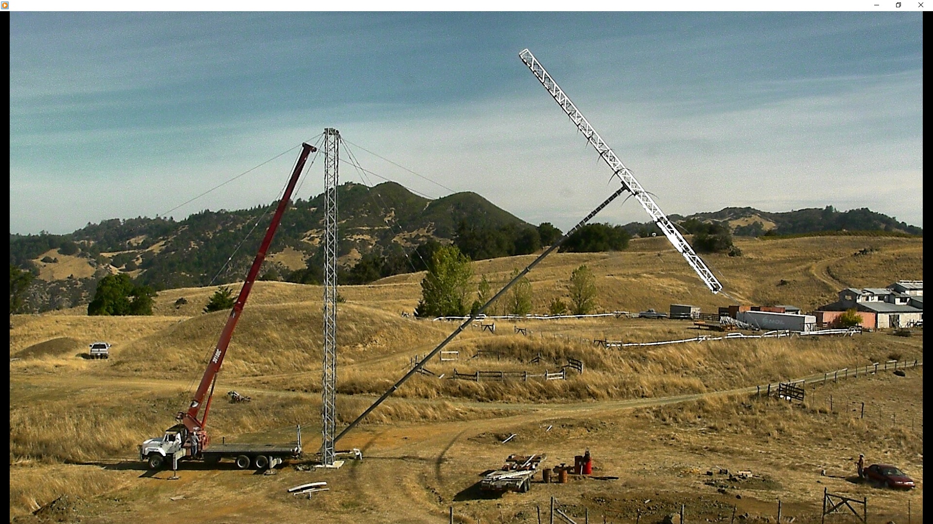
Coming Up
My 8000 pound pull winch was not enough to lift the antenna and mast. I had to hire a crane to assist. It actually took the two of us to get it started, that is, a 35 ton boom truck together with my 8000 pound pull winch truck. The load by itself was lifting the front end of the truck up. Once we got it to about 20 degrees, my truck was able to complete the lift.
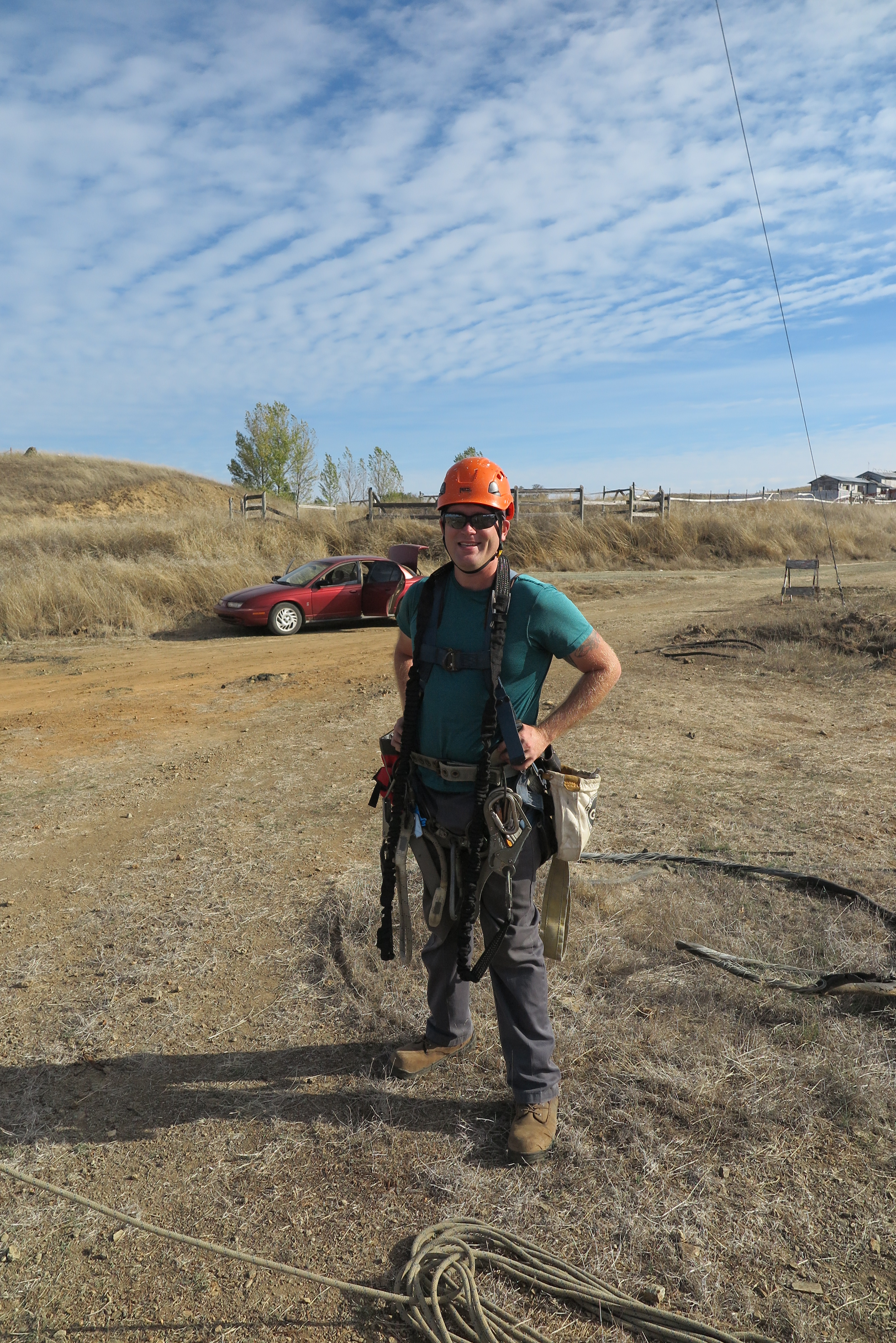
Bill Helping Out
This is my neighbor Bill helping all-around, but here getting ready to replace the T-bar at the end of element 19. We removed both sides before the lift to prevent them from scraping on the ground and getting ruined.
Ready to Bolt Mast Plate
At this angle, we swung the antenna boom up until the mast plate mated with the boom. I roped the back end of the boom to the car, just to keep it from swinging with me on the boom.
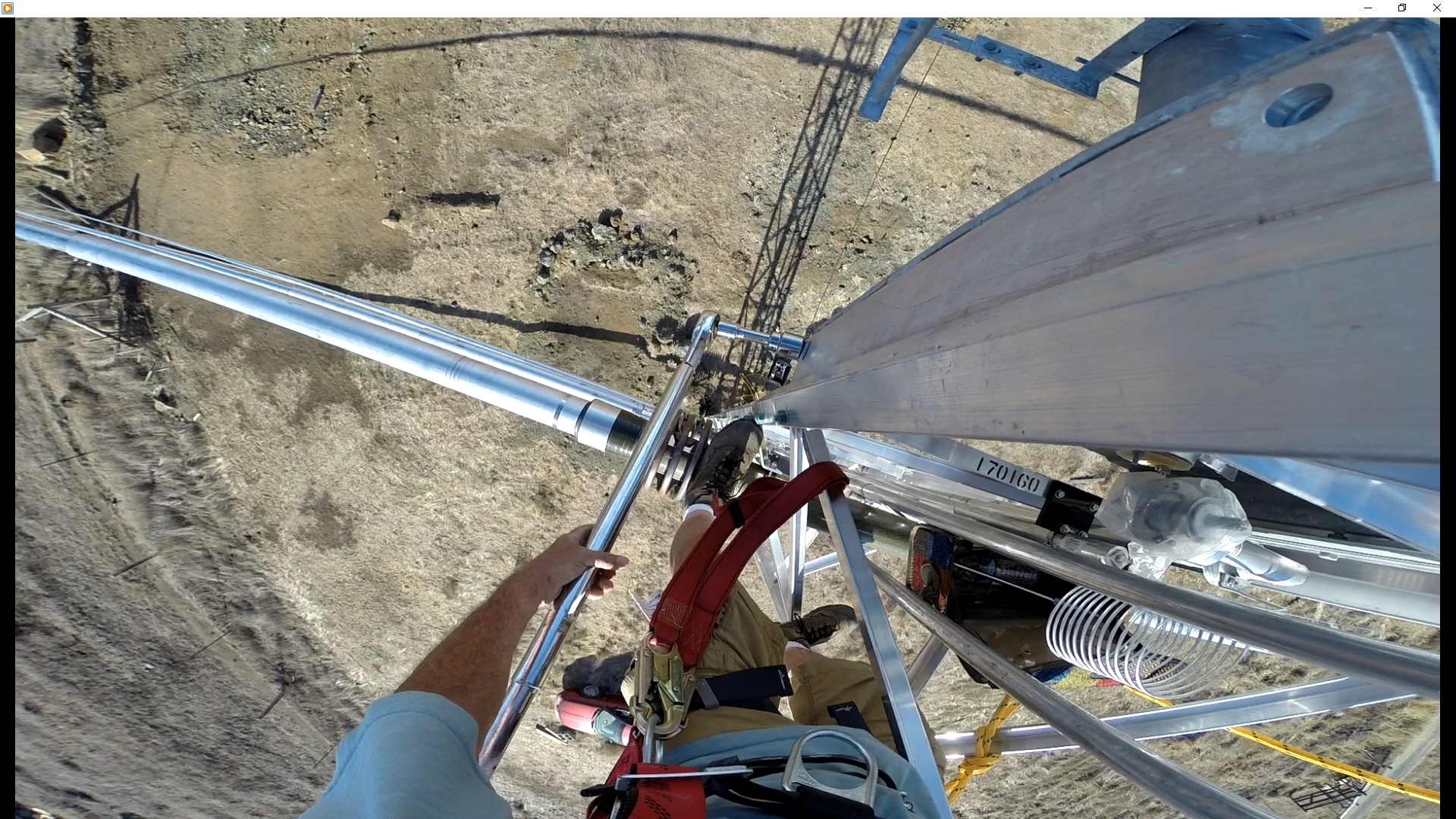
Torquing Bolts
I was able to climb the boom and torque the four bolts that hold the entire antenna up. They required 200 foot pounds.
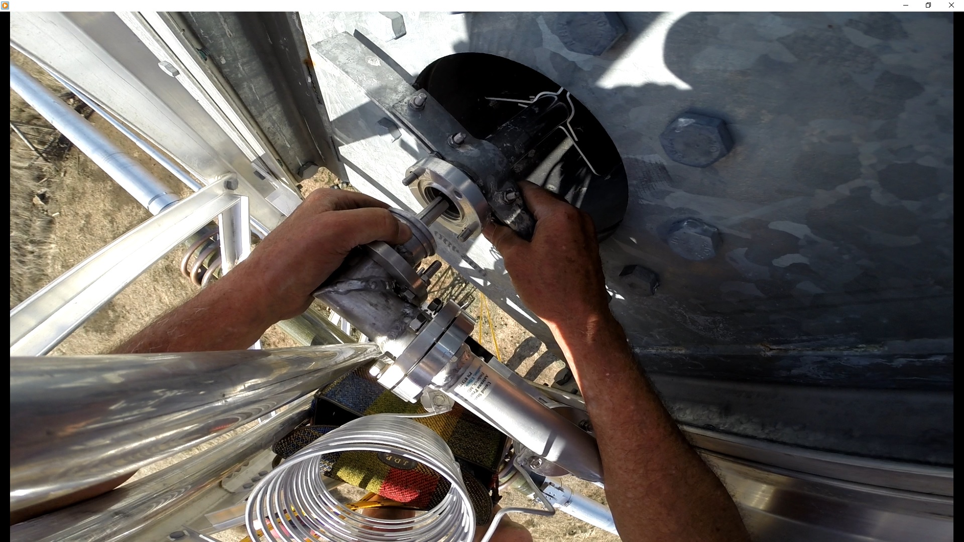
Joining EIA Flanges
The 1 5/8" EIA flanges had to be mated. This is a delicate operation to prevent the O-ring from pinching and effecting a leak. Also, the bullet has to seat perfectly in the center conductor tubes.
Final Flange Bolt Tightening
I am putting the final torque on the flange plates here.
Mast at 50 Degrees
Together, the two winches have the mast up to 50 degrees or so.
View from Winch Truck
In this view from my winch truck, the sun was right in line with the antenna.

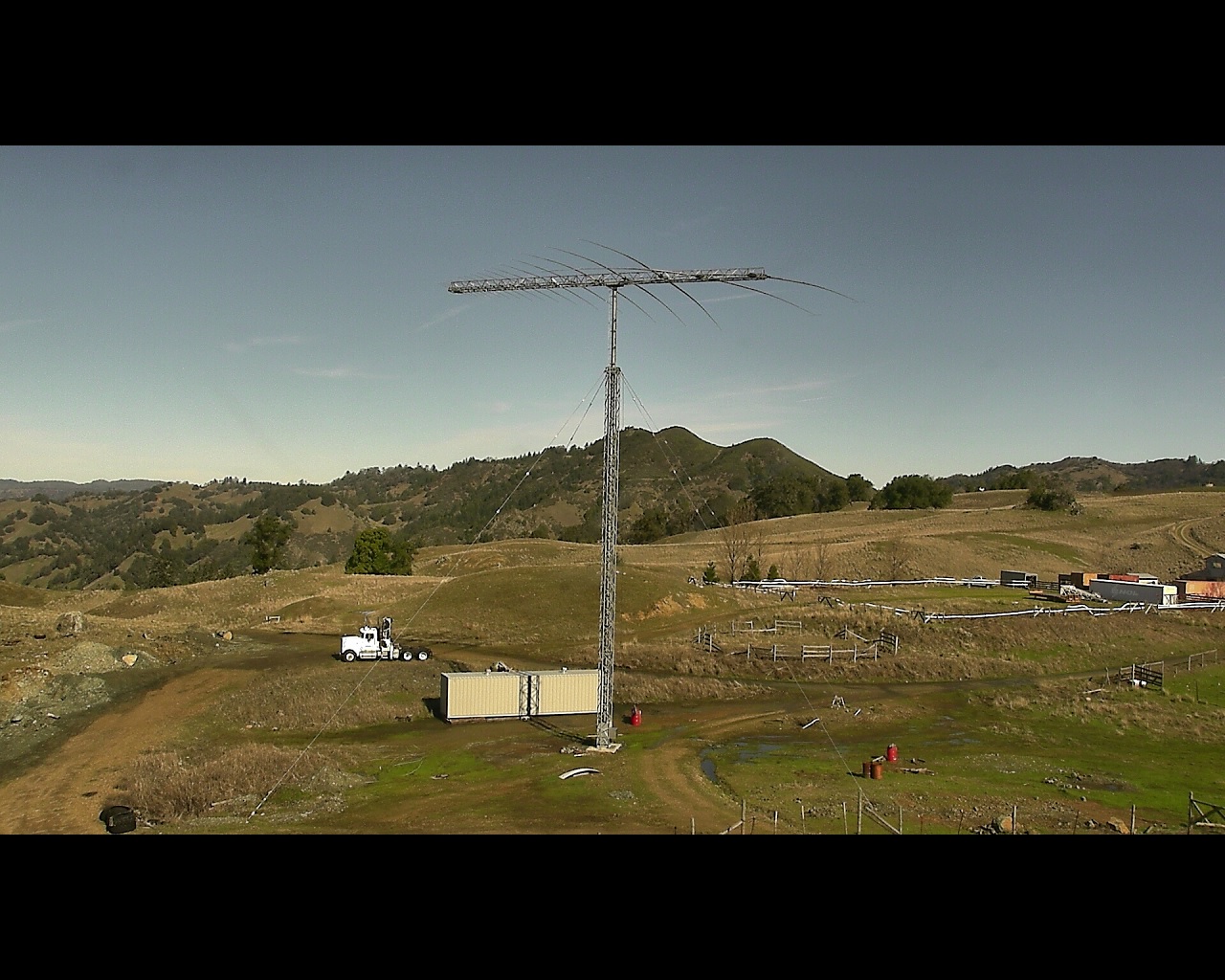
Finally Antenna is Upright
This was a load off, so to speak, seeing the entire structure upright for the first time. Unfortunately, the antenna was just a useless piece of eye candy...
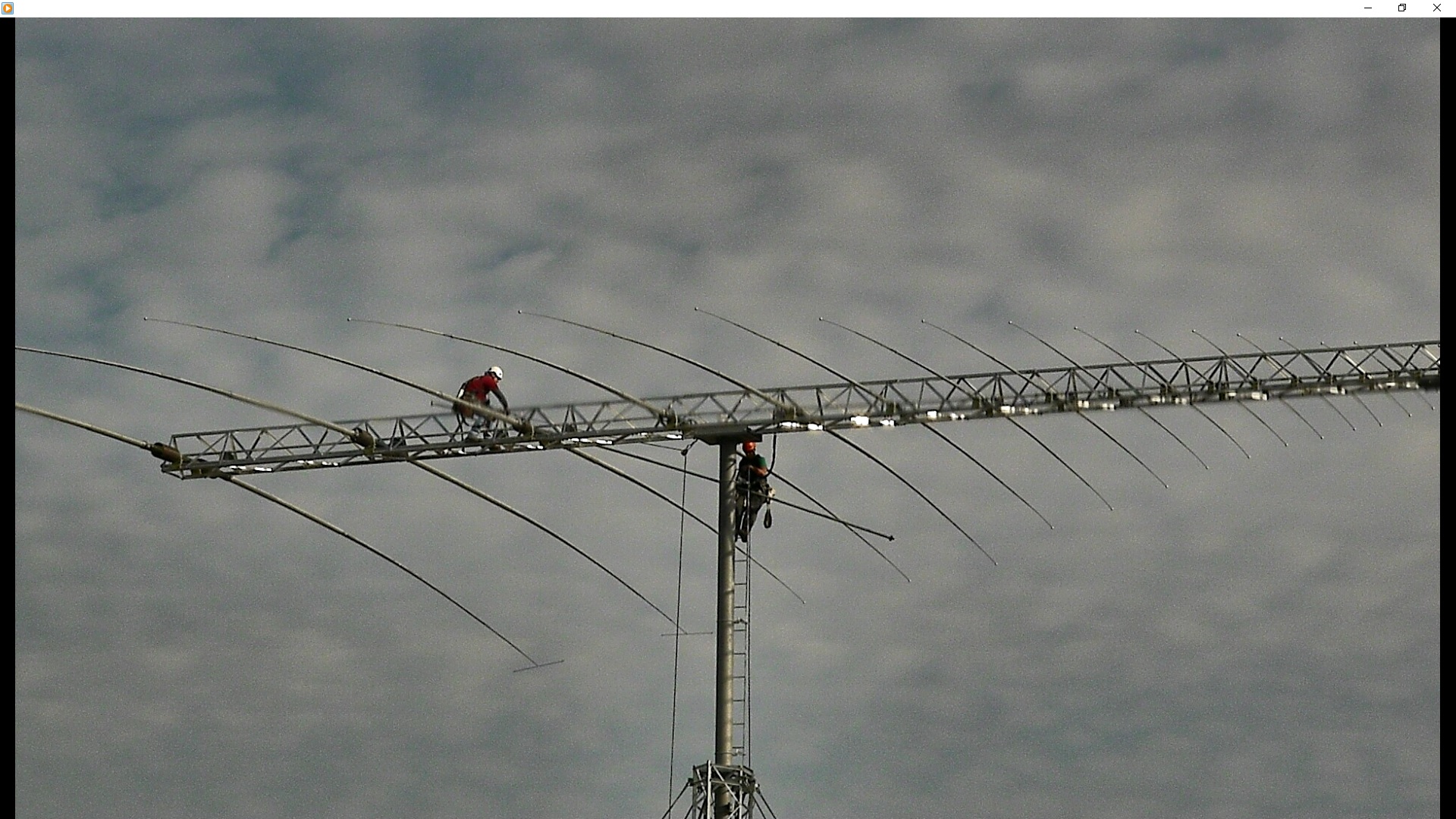
Arriving on Boom
The antenna was up, but the SWR was just as bad as ever, so I acquiesced and hired the company that made the antenna to come out and fix it. Here, Mike and Nick have arrived at the boom to try and figure out what was the problem. They have already checked the guy tension, plumbed the towers, and checked the bolt torque on every bolt on the tower. They found a few loose ones and two bolts completely missing.
Mike Working at Element 19
There is an EIA horseshoe 180 degree fitting on the back of the boom that Mike is about to remove here. This elbow has to come off so the transmission line may be slid backwards to remove the bad section.
Checking Transmission Line
They began by disassembling the transmission line flange joints, looking for incorrect, or miss-installed bullets. They thought they had the culprit in one joint, but no, it was the same transmission line segment that had the ding from the screw that was the problem.
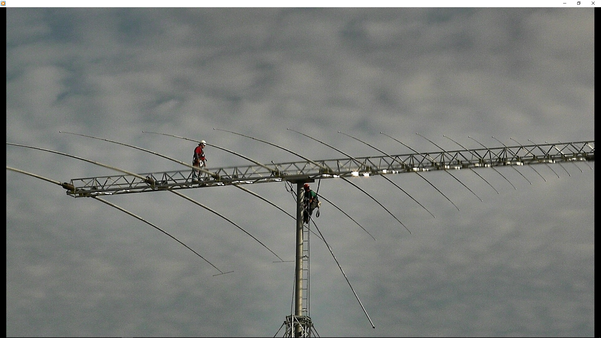
Removing Transmission Line
Mike and Nick are removing the defective transmission line section. These men are not fly-weights, and with their 50 pound harnesses, there was probably 500 pounds or more moving around on that boom. The antenna didn't seem to care; it deflected the mast perceptively, but I was amazed at the strength of the truss boom.
Bad Line
Look at the center conductor. A whole group of the spacers had bunched-up allowing the center conductor to touch the outer coaxial tube. When we pulled the center tube out from the end, it was clear the obstruction was at the flange end. The inner diameter of the aluminum tube was compressed just enough to stop the Teflon spacers from passing through. After we forced the brass center conductor out of there, I honed the inner surface to allow the spacers to pass unobstructed.
This is the transmission line segment that has the perforation from a boxing screw, and the fear was that it had deformed a dimple into the tube which was going to hang up the spacers. I attached one spacer to the center conductor, and slid it into the transmission line. To all our relief, it slid right past the screw perforation, eliminating another potential headache.
Reinstall Transmission Line
Day 3 of the repair with Mike and Nick back on the boom replacing the now repaired transmission line segment.
It's my personal opinion that this transmission line was defective from the get-go, because I never pulled the center conductor more than a foot from either end when I was trying to fix the screw perforation. Of course the perforation was clearly USAP's fault, but the company refused to honor any warrantee. It's my opinion that USAP should have at least shared some of the cost to repair this antenna system since all of the problems are due to lack of quality control at the factory.
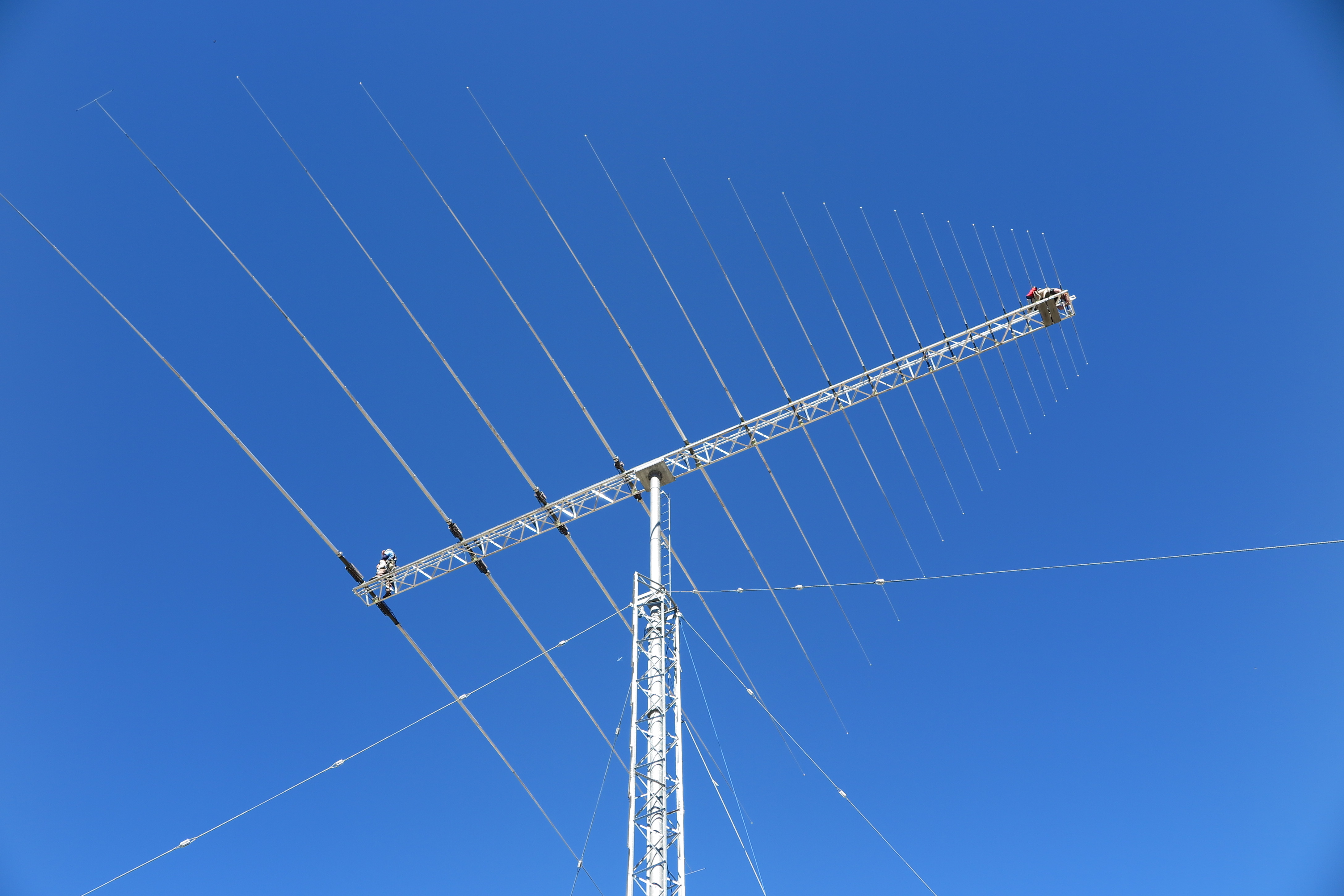
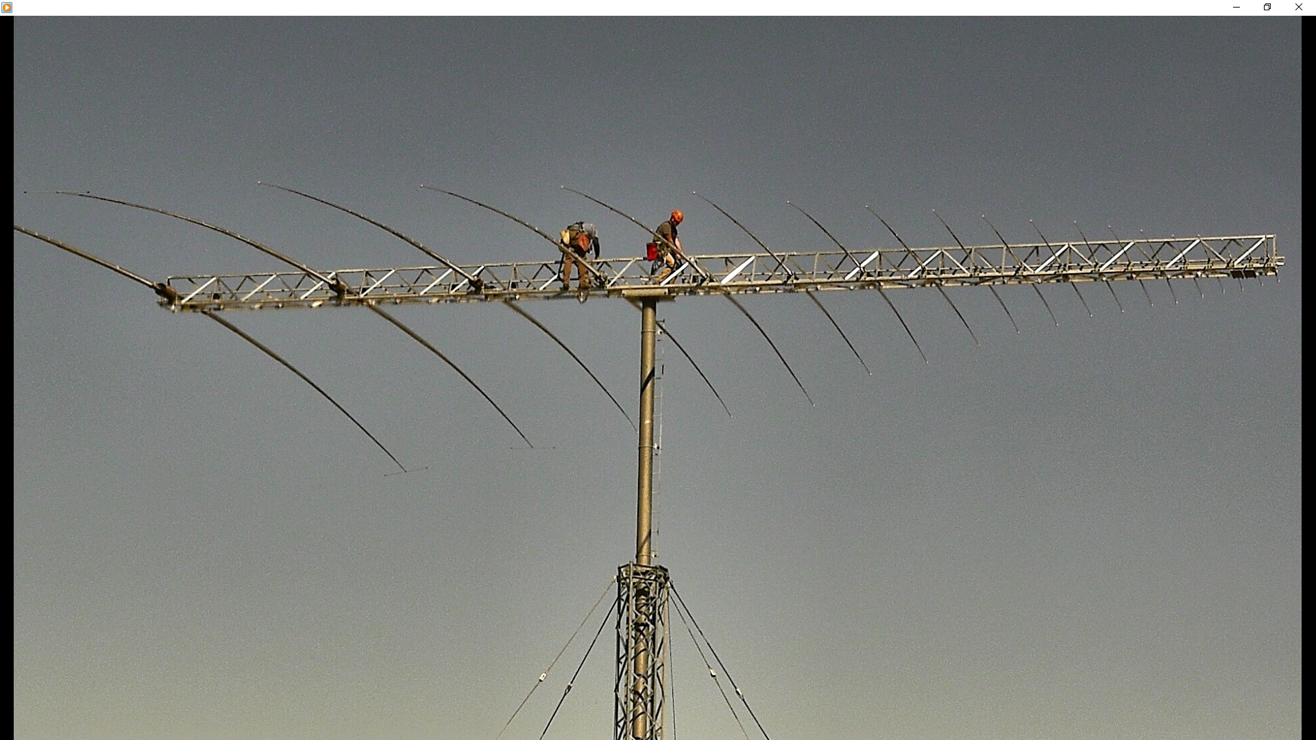
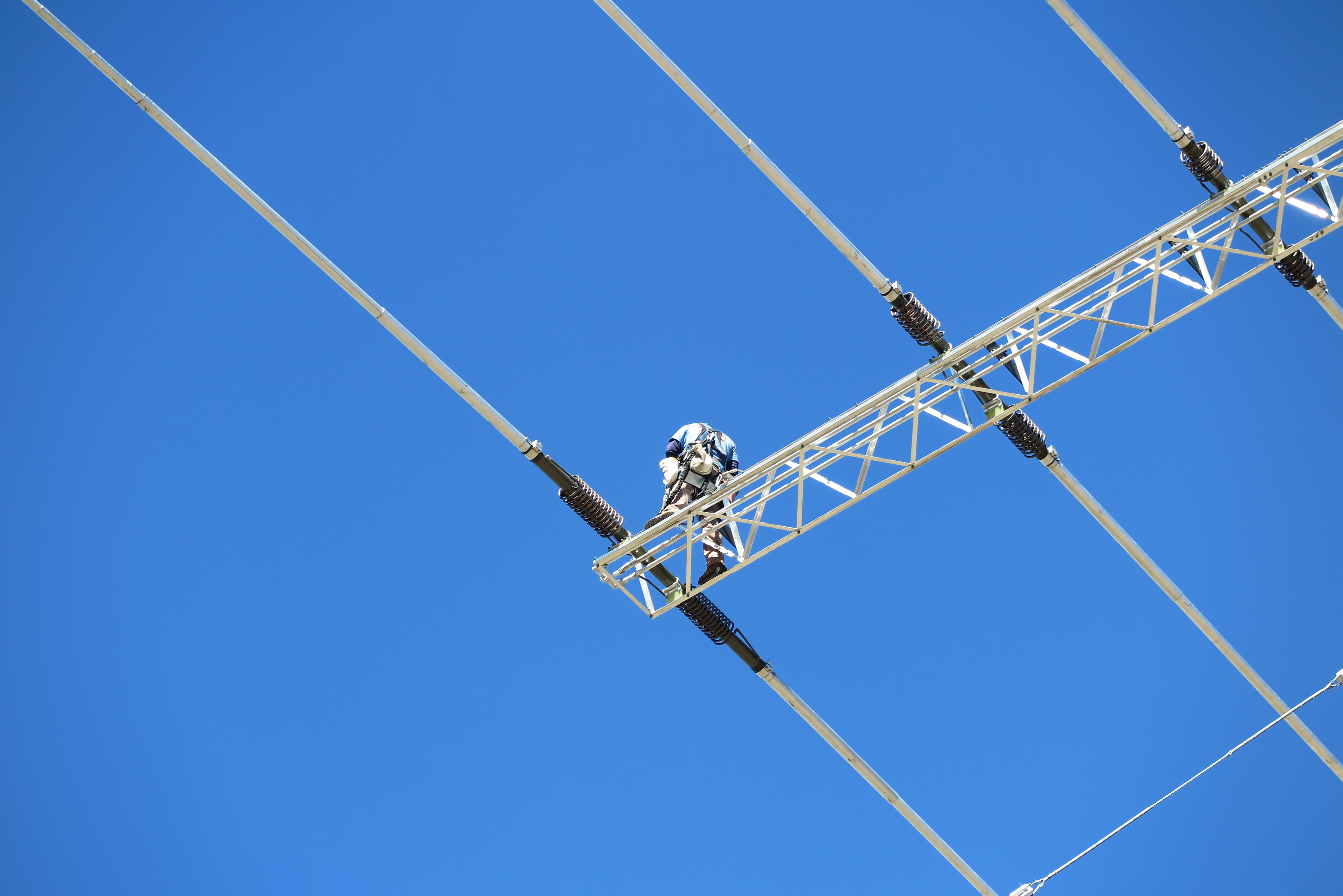
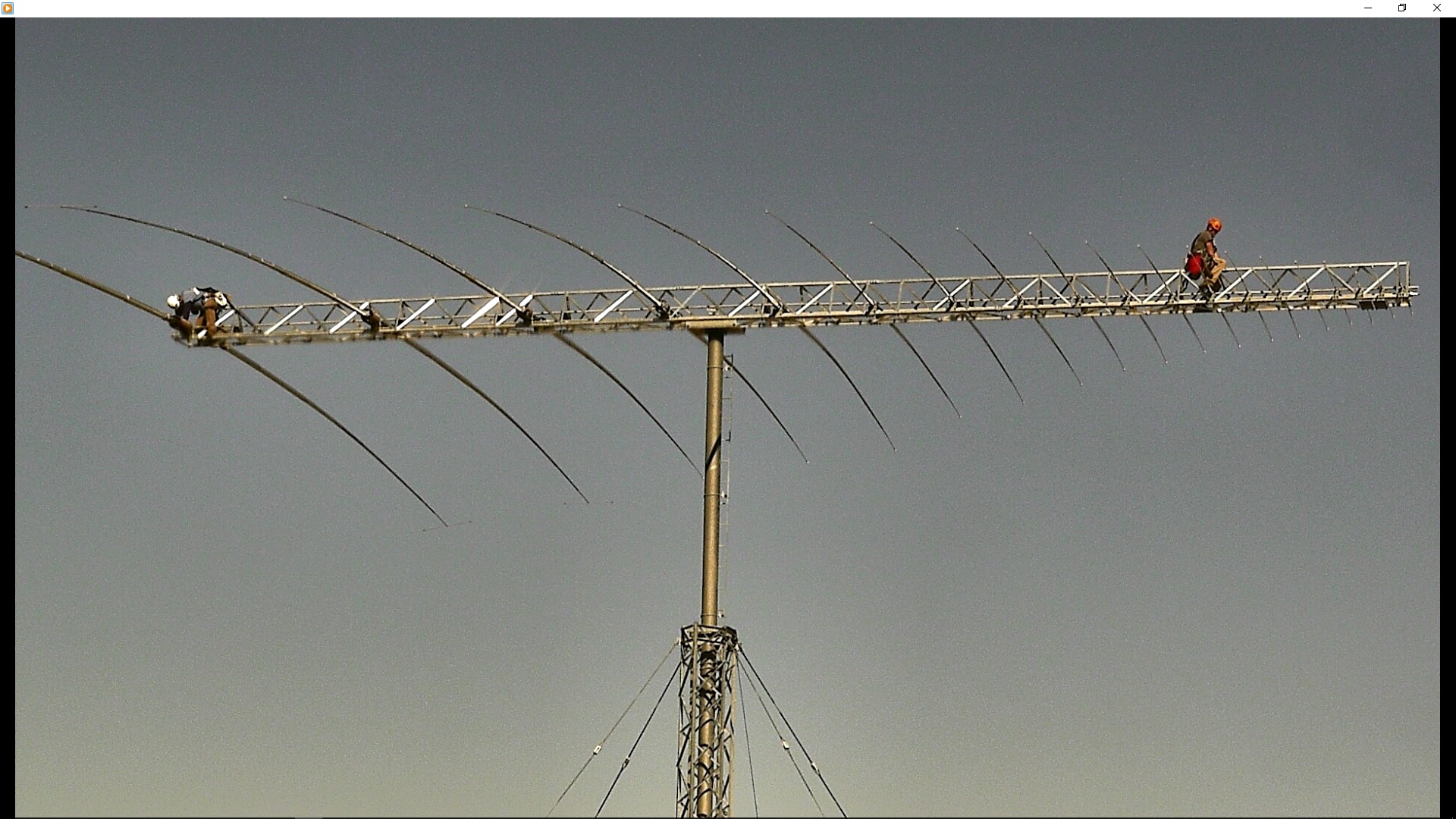
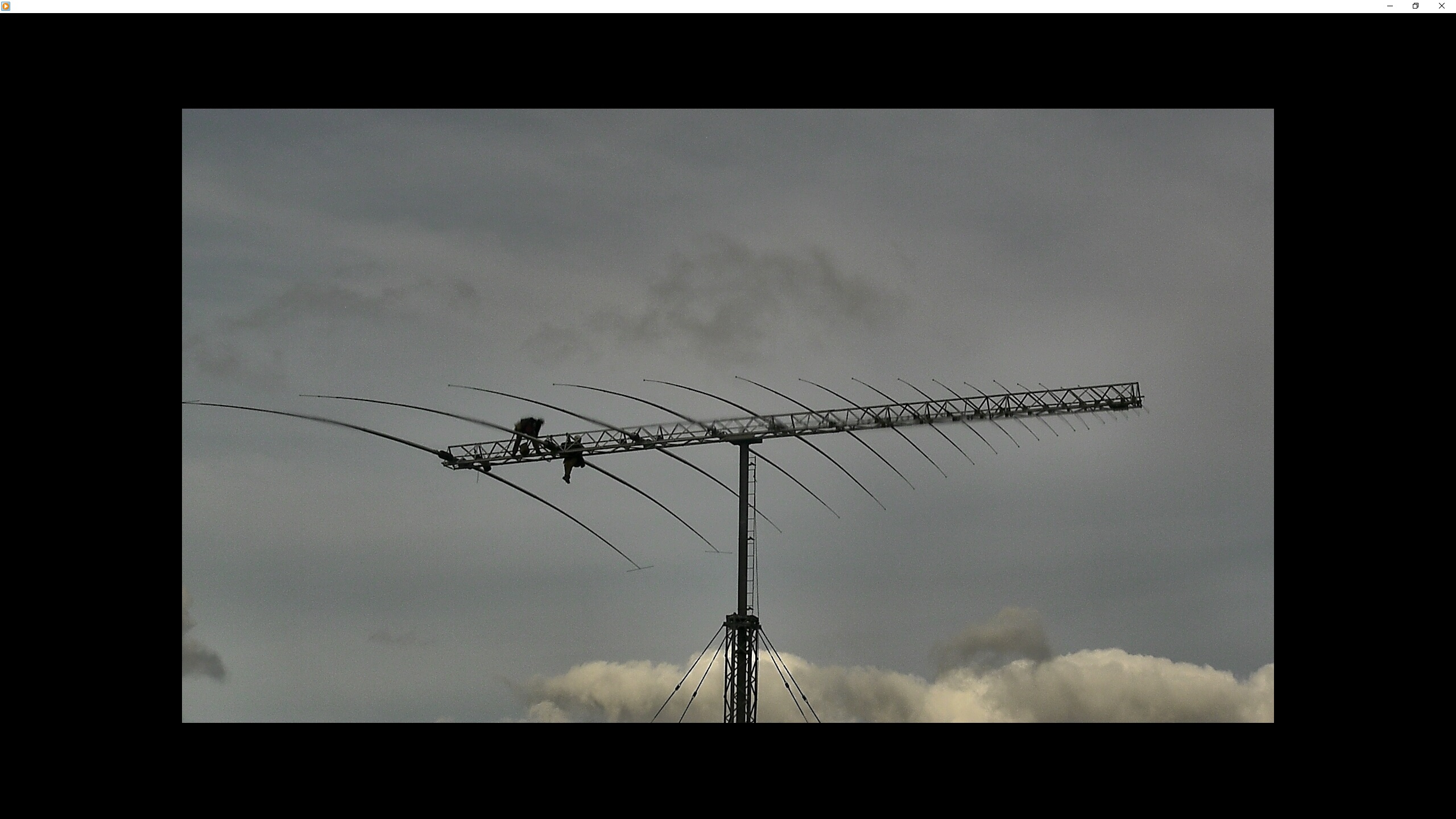
It's a Big Antenna
From this view of Mike and Nick working on the boom, you get a feel for just how large this antenna is.
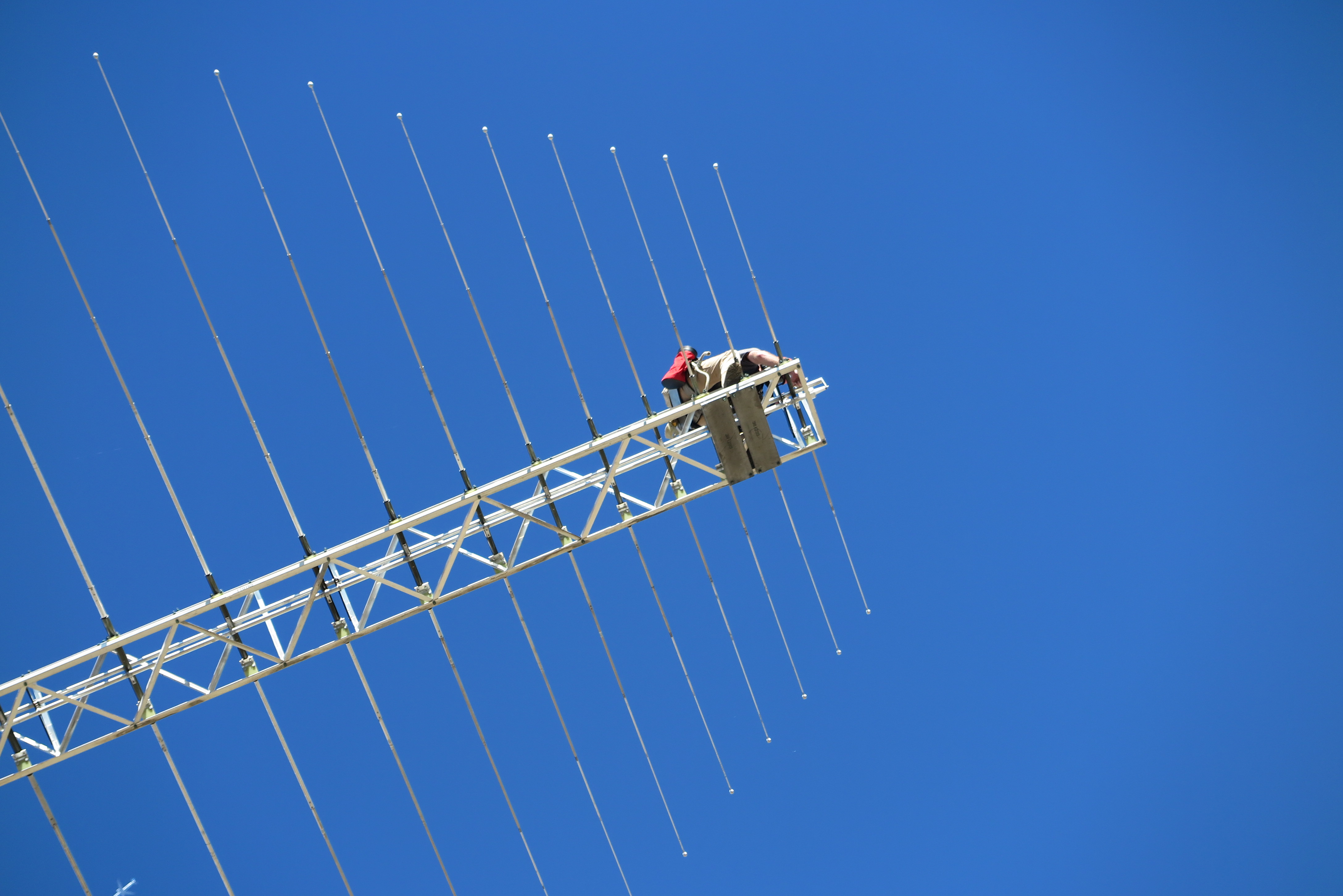
Remove Ice Cream Cone
Nick is removing the EIA coax termination from the nose of the antenna, which has been nicknamed, "the ice cream cone".

Michael Dennis
Mike Dennis from US Tower Services based in Maryland.
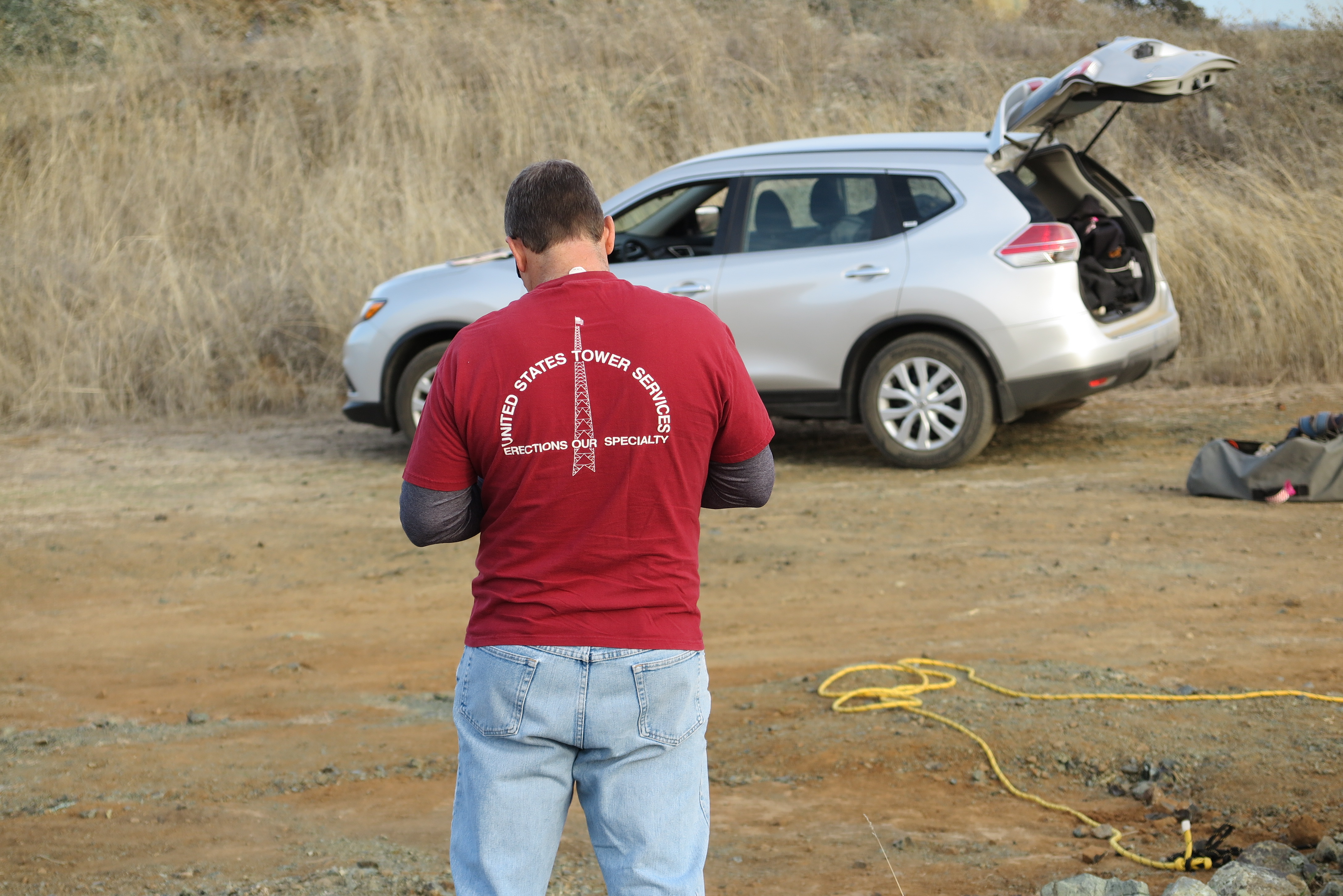
Cool T-Shirt
This picture speaks for itself...
Nick Weigner
Nick Weigner also from US Tower Services.
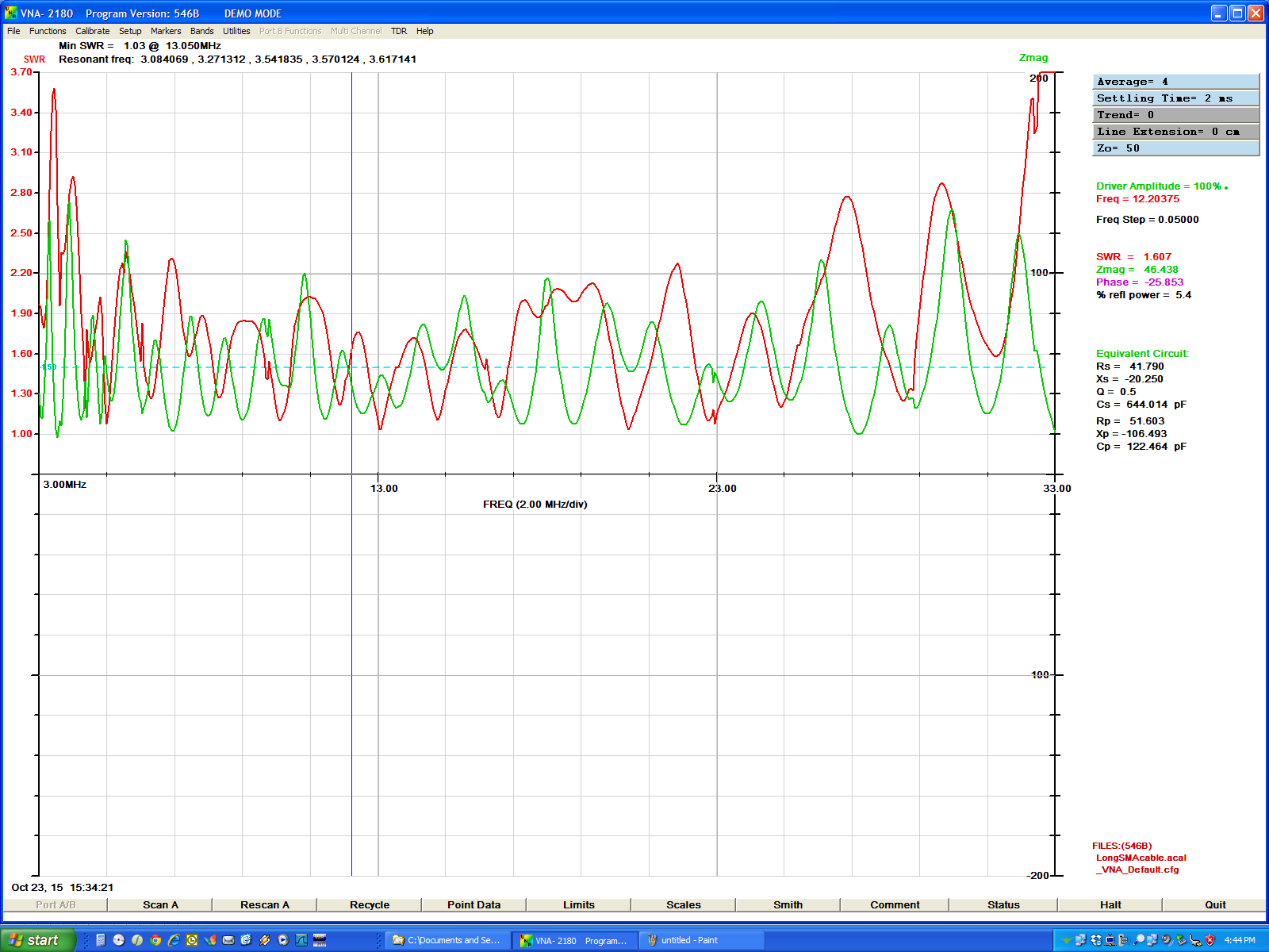
VSWR Post Repair
This is the VSWR plot after the tapered transmission line repair. It is out of spec. The antenna's spec is SWR less than 2:1 from 4 through 30 MHz, and less than 3:1 from 3 through 4 MHz. Also, now there is a loss of pressurization in the line, and I suspect the "ice cream cone" flange area. I suspect that, because the highest excursions in SWR are at the high frequency end where the dipole feed begins. Of course it could be any of the flange interfaces, and I'll have to check them all when I muster the courage to get up on that boom.
Broken Elements 18 and 19
A couple storms into rainy season, with maximum 52 MPH winds, and I find this ugly picture after the storm clears. Elements 18 and 19 have had their attachment U-bolts on the left side snap, and the elements have moved off their mounting plates forward onto the boom frame!
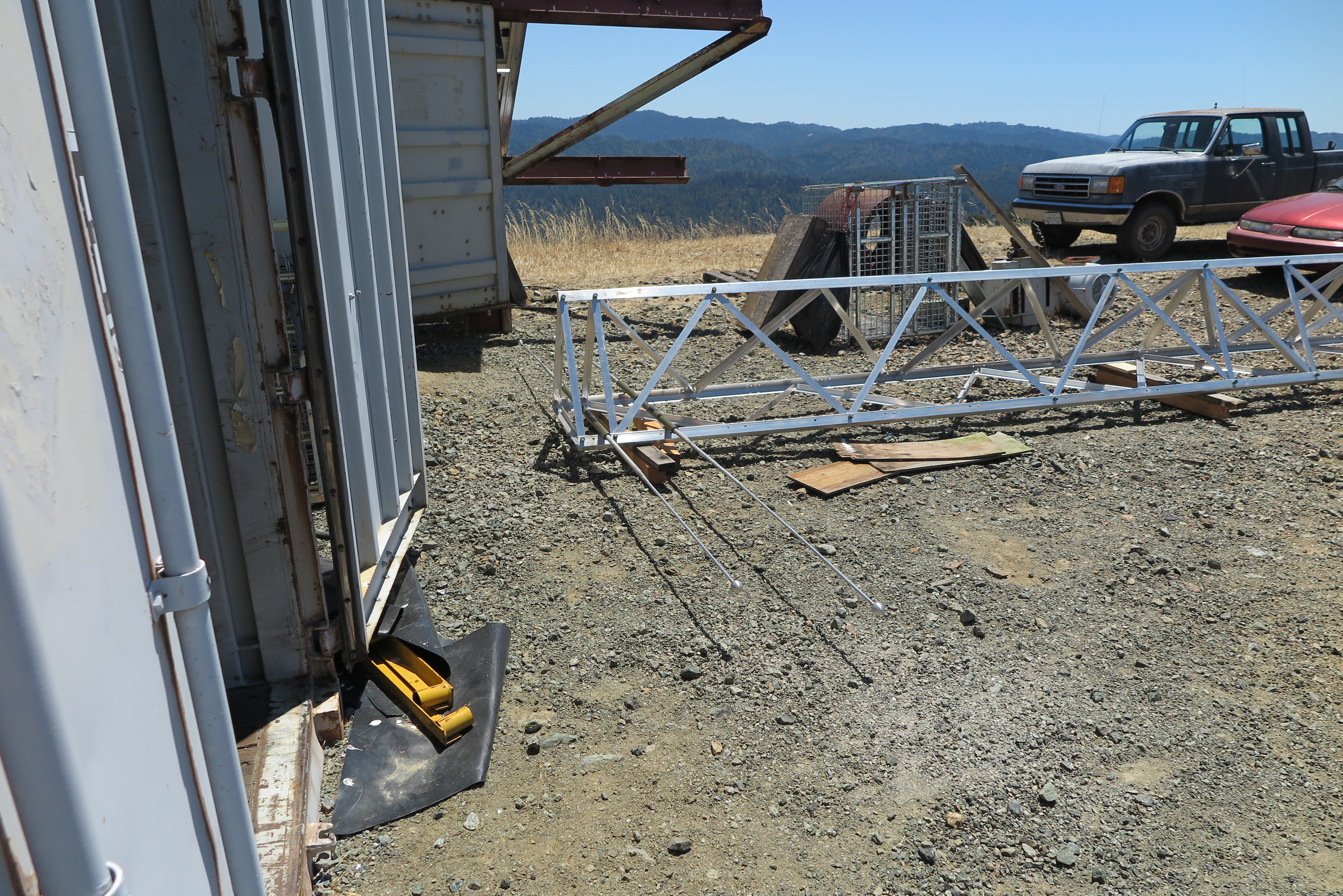
Also note that I now have a "shack" which is to be the 40 foot container I moved in just before the rainy season began.
Snapped U-bolt
In this close-up of Element 19, the snapped U-bolt can be seen on the left side. The element itself has twisted clockwise off its mounting bracket, and is now resting on the boom frame.
The instruction manual said in at least two places: "Do not torque U-Bolts beyond 20 foot pounds to prevent damage to the insulators.". The head technician told me the bolts were loose, and needed tightening, but I had already made sure the U-bolts were at the proper torque before I erected the antenna. Anyway, I assumed he knew what he was doing, and let him tighten all U-bolts on all 19 elements. Obviously, they were all over-torqued, allowing the bolts to snap on the big elements, and creating this new problem.
Repair Team No. 2
I found the attorney for the tower company through their articles of incorporation in the state of Maryland. I prepared a legal Letter of Demand, and e-mailed their attorney some of the highlights. He said he would talk to the company, which admitted their fault, and made an appointment to come to site, and repair the antenna, this time on their nickel.
On this trip, the chief technician from US Tower Services flew out to California, but he hired a local tower worker who just happens to be the chief rigger for Sutro Tower. He was a pretty interesting person to have at site, and a real great contact in case I need further tower work.
In this image, they are repairing the damage to the loading inductors, and replacing the U-bolts. They torqued them to 20 foot pounds, and placed locking nuts on the bolts.
The Sutro rigger was very thorough in his work. He found the air leak in the 1 5/8" EIA transmission line, and fixed it. This leak was created by the first repair when the transmission line terminator was removed and replaced.
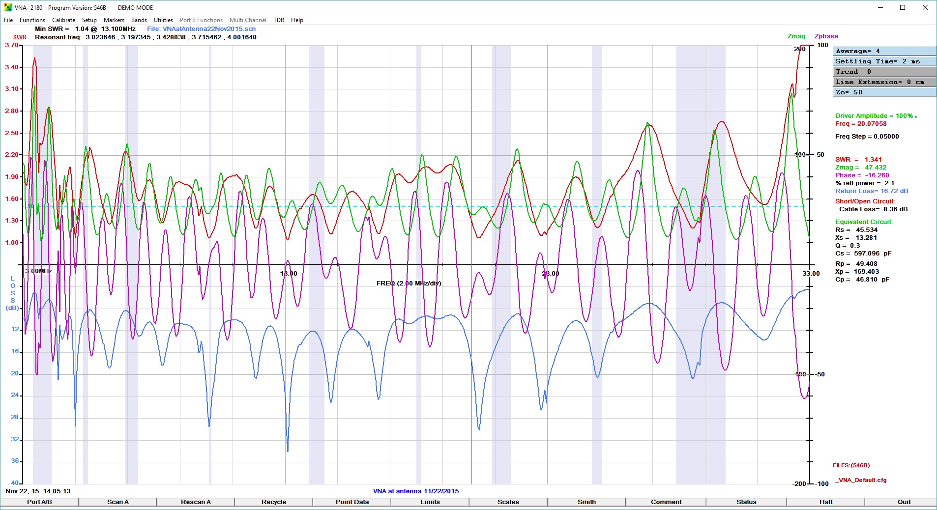
2nd Repair VSWR
Here is another screen shot of the VNA sweep after the second repair. VSWR is still out of spec, and I will need an antenna tuner to get power into the antenna. Buying this Log Periodic with its advertised less-than 2:1 VSWR was the main reason I went for it in the first place, to not have the need for an antenna tuner!
I still plan on bringing the antenna back down this spring, and going over every square inch of it in a final attempt to get the VSWR in spec. The |Z| is generally high across the spectrum, and there may be a flange joint or two without good contact of either the inner conductor or the outer jacket. I'll go over every joint carefully to clean and check the interfaces.
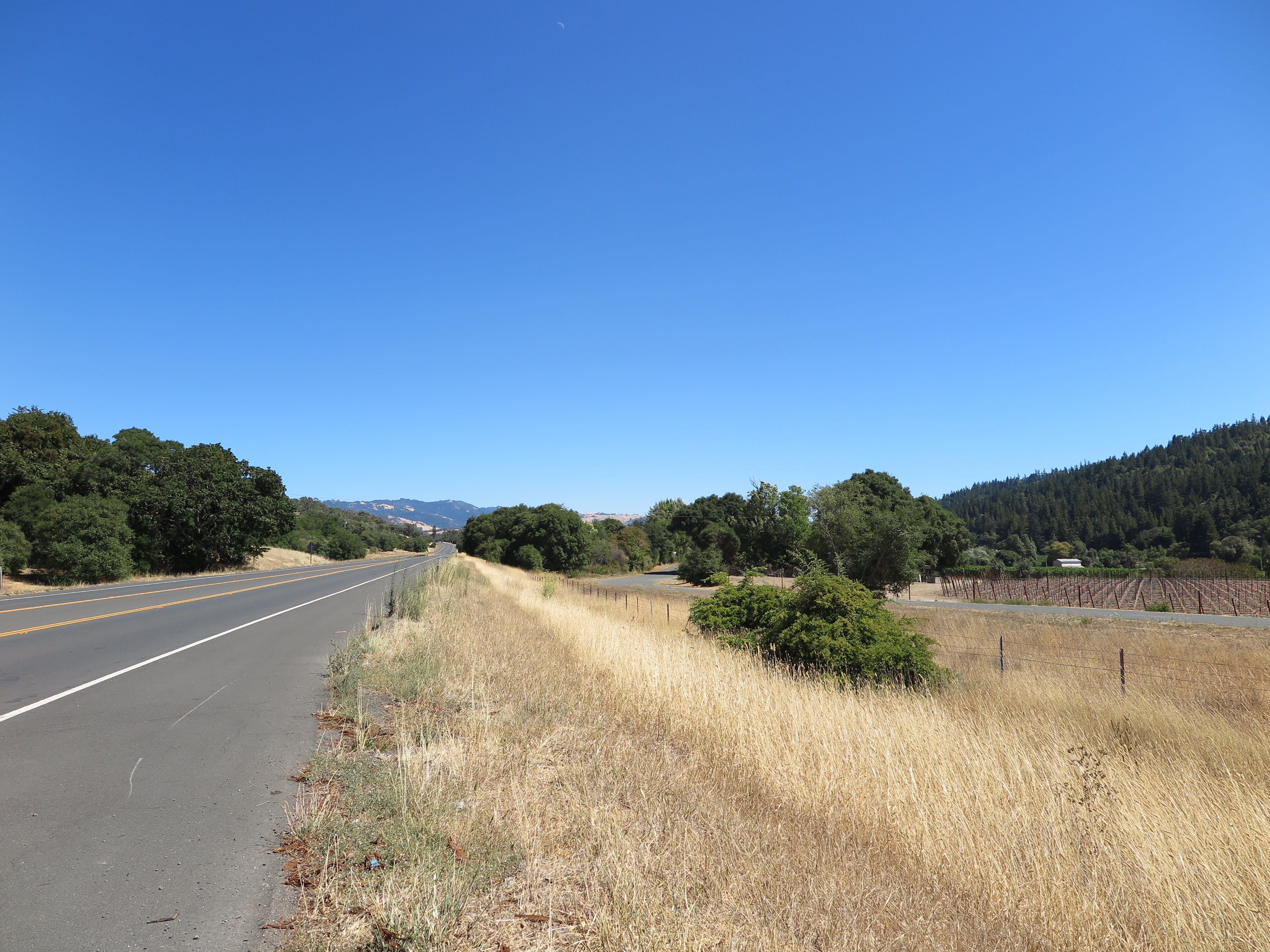
Antenna From 9 Miles
Can you see my antenna? This shot is from 9.02 miles line-of-sight from the antenna site. From the tower, I could see this highway with my field glasses, so on a trip to Ukiah, I decided to find this location. It is about half way between Boonville, and Philo California along Highway 128 headed to Mendocino on the Pacific coast.
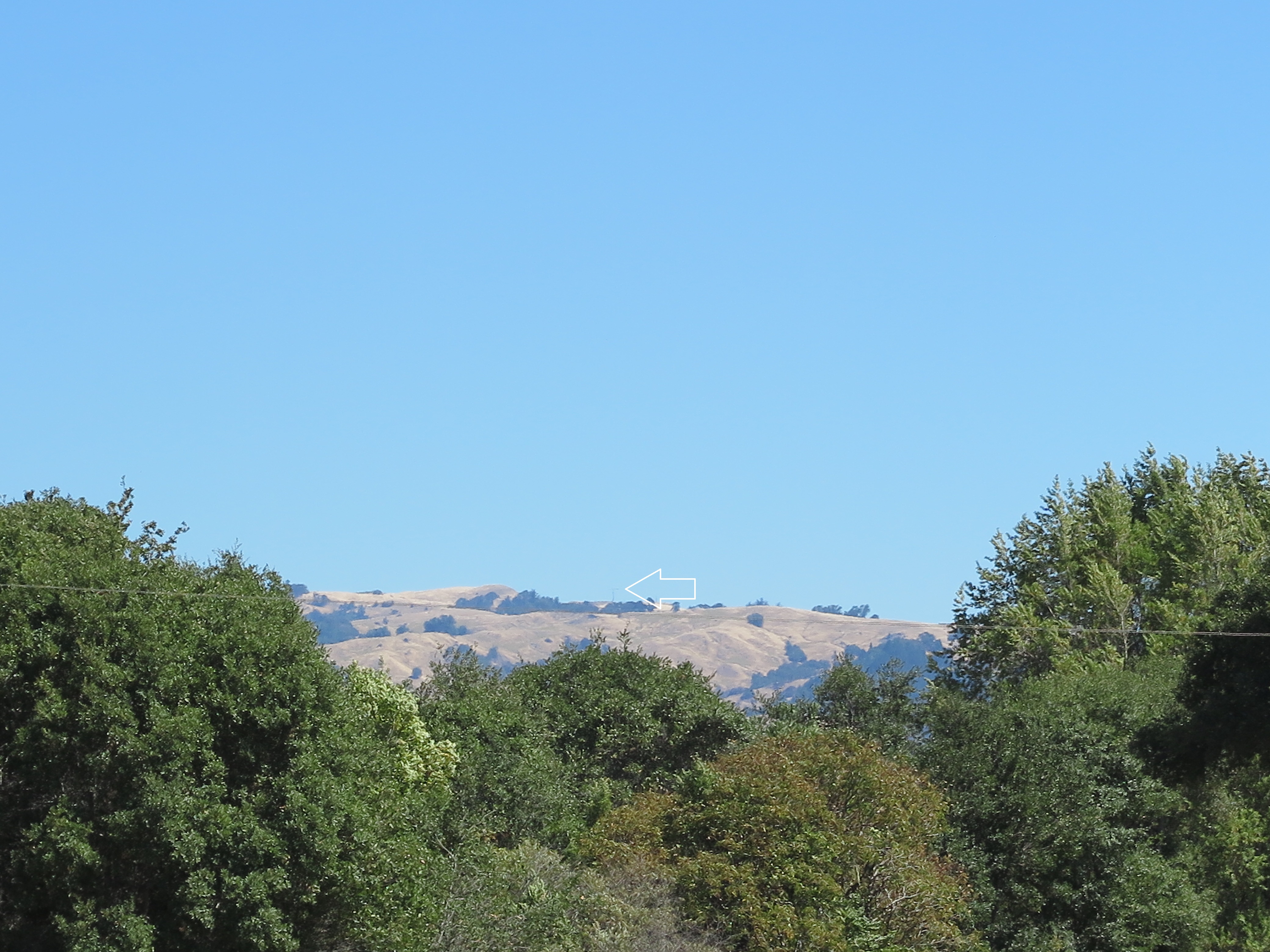
Zoomed into Antenna along Hwy 128
Okay, I zoomed the camera from the same location as the previous image, and placed an arrow pointing at the antenna. The distance, line-of-sight is 9.02 miles.
You can click on any of the images to download a full resolution version, and then if you click on the new image, it will magnify one level making the antenna and tower visible.
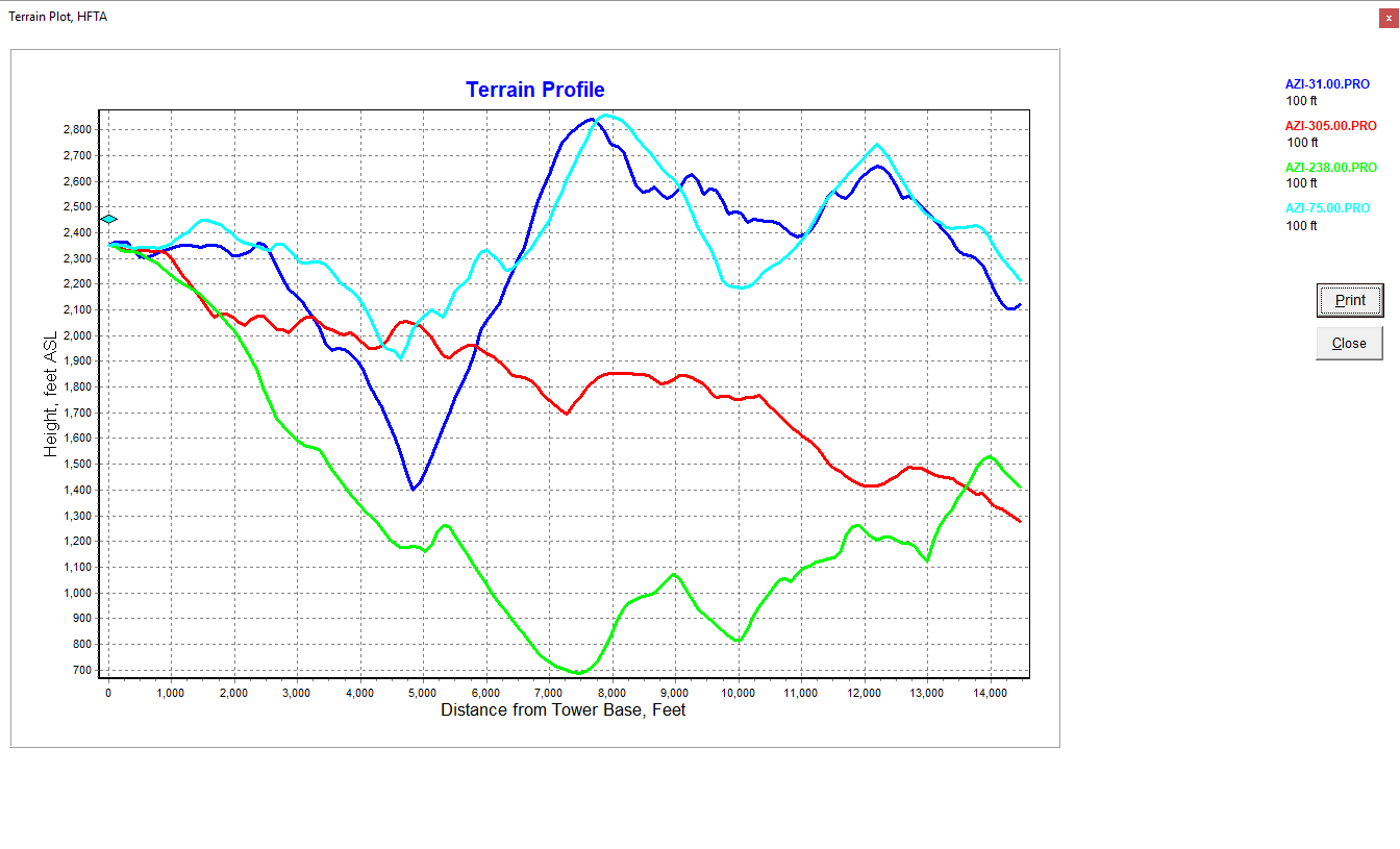
Terrain Graph at Four Directions
Here is a terrain profile with the antenna pointed in four different directions.
Dark Blue is the antenna pointed toward Europe. Light Blue is with the antenna pointed to the east coast of USA. Red is with the antenna pointed toward Japan, and Green is toward Australia.
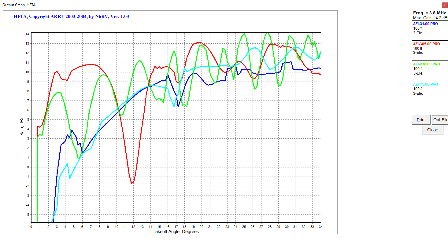
80 Meter Gain vs Takeoff Angle at Four Directions
Here is a gain vs takeoff angle plot at 80 meters with the antenna pointed in four different directions.
Dark Blue is the antenna pointed toward Europe. Light Blue is with the antenna pointed to the east coast of USA. Red is with the antenna pointed toward Japan, and Green is toward Australia.
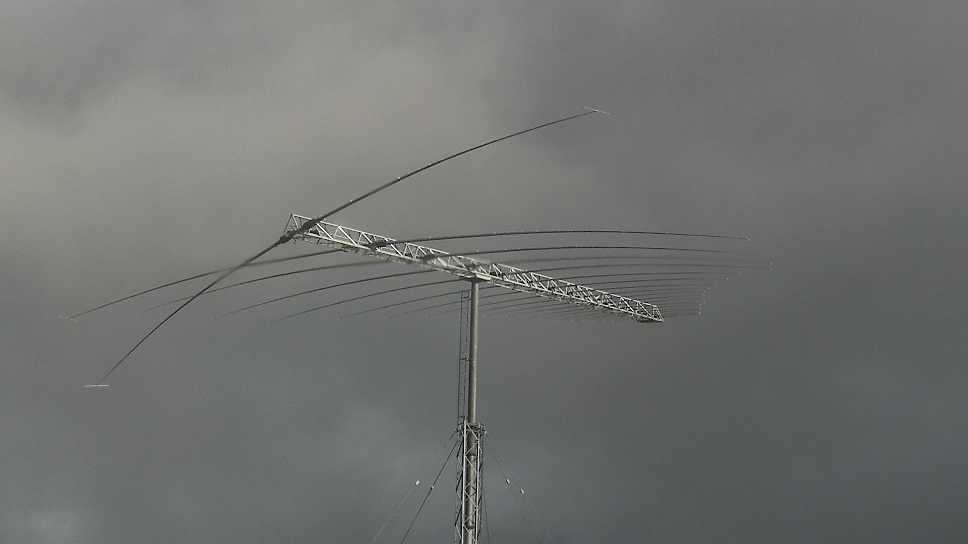
Element 19 snapped the U-Bolts again!
Here we are January 2019, after a storm with winds to 55 MPH, and the antenna is broken again! The U-Bolts holding the large element 19 have snapped just like before.
I emailed US Antenna Products to ask if I could hire them to repair it (again) - no response at all. I think any person, government, or company that buys an antenna from US Antenna Products is nuts...
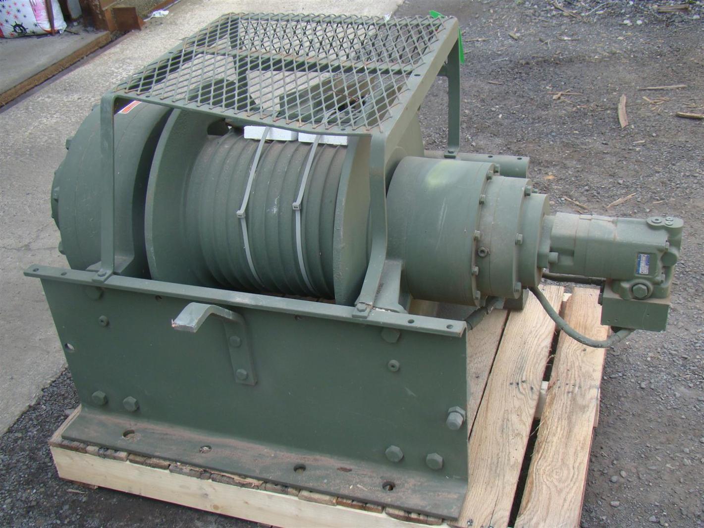
Winch to Lower Antenna
I purchased a surplus winch similiar to this to lower the antenna in the spring, and repair it myself. The winch I purchased has the wire rope on the drum unlike this sample. The winch can pull 55,000 pounds which should leave plenty of margin with this antenna. I will have to pour a concrete foundation to hold a force of that nature, but not until spring arrives...